Novel air film cooling slotting structure

A new type of film cooling technology, which is applied in the direction of supporting components of blades, engine components, machines/engines, etc., can solve the problems of reduced cooling effect and limited lateral cooling protection effect, so as to reduce strength and improve film cooling efficiency , reduce the effect of penetration

Active Publication Date: 2016-08-03
HEBEI UNIV OF TECH
View PDF8 Cites 4 Cited by
  • Summary
  • Abstract
  • Description
  • Claims
  • Application Information

AI Technical Summary

Problems solved by technology

For example, the Chinese patent No. ZL200710017790.4 discloses a slotted film cooling hole. The film cooling hole includes a first transverse groove and a second transverse groove. The first transverse groove is provided with a pointed tongue to ensure The lateral diffusion of the cooling air in the first horizontal groove is improved, but the lateral cooling protection effect on the downstream of the horizontal groove is limited, and the cooling effect is obviously reduced when the blowing ratio is greater than 1.0.

Method used


Image

  • Novel air film cooling slotting structure
  • Novel air film cooling slotting structure
  • Novel air film cooling slotting structure

Examples


Embodiment 1

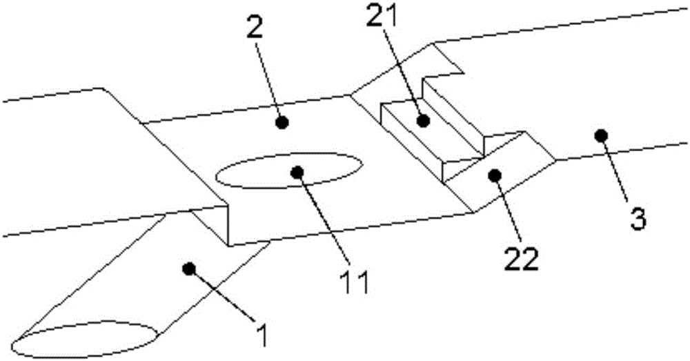
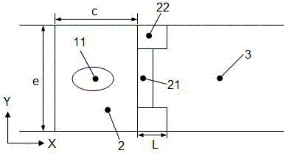
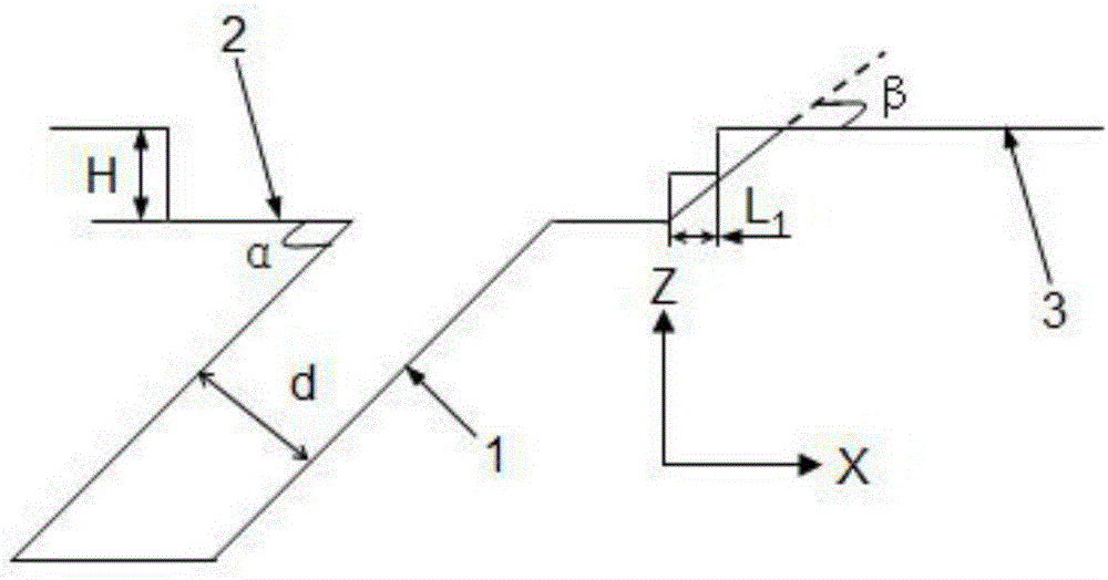
[0033] The structure of this embodiment (see Figure 1-4 ) includes air film hole 1, transverse groove 2 and wall surface 3, air film hole 1 is arranged on the upstream area of ​​wall surface 3, and transverse groove 2 is provided at the outlet of air film hole 1, and the downstream groove wall of transverse groove 2 There is a downstream ladder 21 at the middle position on the top, and the guide surfaces 22 are arranged symmetrically on both sides of the downstream ladder 21. The plane of the downstream ladder facing the incoming flow direction is perpendicular to the wall surface, and the lowest point and the highest The points are respectively flush with the bottom surface of the transverse groove 2 and the downstream wall surface 3, and the downstream step 21 is arranged axisymmetrically with the center of the air outlet hole 11 of the air-passing film hole and parallel to the center line of the wall surface 3; The wall surface 3 is a slope with an included angle of 15°-75...

Embodiment 2

[0040] The composition and relative positional relationship of each part in the structure of this embodiment is the same as that of Embodiment 1, and the number of steps of the downstream steps is 2. The difference is that the sizes of the two steps of the downstream steps in this embodiment are not exactly the same. The length of the step in the Y direction is greater than that of the following step, the ratio of the maximum projected length of the downstream step along the lateral direction of the wall (ie the Y direction) to the aperture of the air film hole is 2.0, and the top view of the diversion surface 22 is a right-angled trapezoid.

Embodiment 3

[0042] The composition and relative positional relationship of each part in the structure of this embodiment is the same as that of Embodiment 1, the difference is that the number of steps of the downstream step is one, and it is a step with an inclined surface.

[0043] What is not mentioned in the present invention is applicable to the prior art.


PUM


Abstract

The invention relates to a novel air film cooling slotting structure which comprises an air film hole, a transverse slot and a wall face. The air film hole is formed in the upstream area of the wall face, and the transverse slot is formed in an outlet of the air film hole. The novel air film cooling slotting structure is characterized in that a down-flow stair is formed at the middle position of the downstream slot wall of the transverse slot of the structure; flow guide faces are symmetrically arranged on the two sides of the down-flow stair; the plane, in the incoming flow direction, of the down-flow stair is perpendicular to the wall face; the lowest point of the down-flow stair is flush with the bottom face of the transverse slot, and the highest point of the down-flow stair is flush with the downstream wall face of the transverse slot; the down-flow stair is arranged symmetrically with the center line as an axis, wherein the center line passes through the center of an air outlet hole of the air film hole and is parallel to the wall face; a slope with the included angle ranging from 15 degrees to 75 degrees is formed between each flow guide face and the wall face; and the ratio of the maximum projection longitudinal length of one step of the down-flow stair in the expanding direction of the wall face to the aperture of the air film hole ranges from 0.25 to 1.0, and the ratio of the maximum projection length of the down-flow stair in the transverse direction of the wall face to the aperture of the air film hole ranges from 1.0 to 4.0.

Description

technical field [0001] The invention relates to the technical field of gas turbine heat transfer and cooling, in particular to a novel gas film cooling slot structure. Background technique [0002] At present, gas turbines are widely used in aviation, navigation, transportation and thermal power generation. Its development represents a country's scientific and technological level, military development and comprehensive national strength. In order to further improve the economy of the gas turbine, the most effective method is to increase the initial temperature of the inlet of the gas turbine. However, due to the limitation of high temperature resistant materials, some effective measures should be taken after the initial temperature of the inlet of the gas turbine is increased. Reduce the working environment temperature of high-temperature components to ensure the safe and reliable operation of the gas turbine. In the cooling system of gas turbine, the film cooling technolog...

Claims


Application Information

Patent Timeline
Patent Type & Authority Applications(China)
IPC IPC(8): F01D5/18
CPCF01D5/186
Inventor 王进翟郑佳崔沛李倩倩闵春华朱恒宣
Owner HEBEI UNIV OF TECH
Why Eureka
Try Eureka