

Scroll compressor
A scroll compressor and a stationary scroll technology, applied in the field of compressors, can solve problems such as unfavorable lubricating oil passage, pores easily blocked by impurities, and increased processing difficulty.
- Summary
- Abstract
- Description
- Claims
- Application Information
AI Technical Summary
Problems solved by technology
Method used
Image

Examples
Embodiment 2
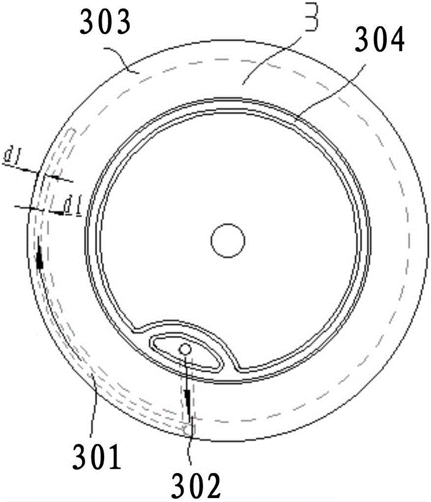
[0054] see Figure 3a to Figure 3c The technical solution of the second embodiment has the following differences from the technical solution of the first embodiment above: In this embodiment, the sub-channel 108 is only provided on the peripheral edge of the fixed scroll 3 .
[0055] see Figure 3a to Figure 3c , the subchannel 108 includes a first throttling groove 301 disposed on the peripheral edge of the fixed scroll 3 . The first throttling groove 301 is arranged inside the fixed scroll 3 and the radian of the first throttling groove 301 is consistent with the radian of the fixed scroll 3 . The peripheral edge of the fixed scroll 3 is a first boss 303 , and the first throttling groove 301 is arranged inside the first boss 303 . The channel 100 also includes a first introduction hole 302 provided on the fixed scroll 3 and a second introduction hole 102 provided on the bracket 1 . Wherein, the fluid flows to the back pressure chamber 9 through the exhaust chamber 6 , the...
Embodiment 3
[0058] see Figure 4a to Figure 4c , the technical solution of the third embodiment has the following differences from the technical solution of the first embodiment above: In this embodiment, the sub-channel 108 is only provided on the peripheral edge of the bracket 1 . Figure 4c The middle arrows indicate the introduction of back pressure fluid flow paths.
[0059] Such as Figure 4a to Figure 4c As shown, the sub-channel 108 includes a second throttling groove 101 disposed on the peripheral edge of the bracket 1 , the second throttling groove 101 is disposed inside the bracket 1 and the arc of the second throttling groove 101 is consistent with the arc of the bracket 1 . The peripheral edge of the bracket 1 is a second boss 103 , and the second throttling groove 101 is arranged inside the second boss 103 . The channel 100 also includes a first introduction hole 302 provided on the fixed scroll 3 and a second introduction hole 102 provided on the bracket 1 . Wherein, the...
PUM
 Abstract
Description
Claims
Application Information