Near-field antenna apparatus for three-segment type metal rear cover

A near-field antenna and metal back cover technology, applied in the field of wireless communication, can solve the problems of high cost, large space occupation, damage to the integrity of the metal back cover, etc., and achieve price saving, high degree of freedom, good cost advantage and space advantage Effect

Inactive Publication Date: 2016-08-03
HUIZHOU SPEED WIRELESS TECH CO LTD
View PDF7 Cites 30 Cited by
  • Summary
  • Abstract
  • Description
  • Claims
  • Application Information

AI Technical Summary

Problems solved by technology

This method takes up a lot of space and is expensive, and the

Method used


Image

  • Near-field antenna apparatus for three-segment type metal rear cover
  • Near-field antenna apparatus for three-segment type metal rear cover
  • Near-field antenna apparatus for three-segment type metal rear cover

Examples


Embodiment 1

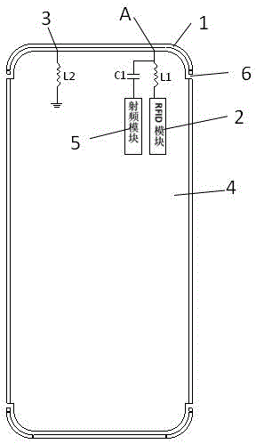
[0029] Such as Figure 1-4 As shown, a near-field antenna device with a three-stage metal back cover is used in a communication device with a metal back cover with a three-stage structure formed by slits at the joints between the upper and lower ends of the metal frame and the metal back cover. Near-field communication is realized without other devices such as coils, and it does not affect each other with far-field RF communication, and signal interference is minimally controlled. The metal back cover includes the first section composed of the upper end of the metal frame 1. The second section 2 is composed of the middle part of the metal frame and the metal back shell, and the third section 3 is composed of the lower end of the metal frame. The dual antenna solution of this embodiment is set on the first section 1 and the second section 2.

[0030] Such as figure 1 As shown, the antenna device is mainly composed of a metal frame section 1 as a radio frequency antenna radiato...

Embodiment 2

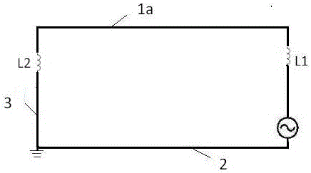
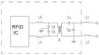
[0038] Such as Figure 6 As shown, as another embodiment of the present application, the difference from Embodiment 1 is that this embodiment discloses a structure of a near-field antenna sharing a metal back cover and a radio frequency antenna feed point device, and the radio frequency module passes B Point A is fed, and the RFID module is fed through A point. The front ends of both modules go through different reactive elements to the metal frame 1 segment. When the RFID module is working, C1 exhibits high impedance characteristics and is in an open state, and the RF module will not affect the RFID antenna. When the radio frequency module is working, L1 and L2 show high impedance characteristics to the radio frequency module and will not affect the radio frequency antenna.

[0039] Such as Figure 7 Shown is the distribution diagram of the RFID loop current at the sub-feed point. The RFID module feeds the RFID antenna through the first high-Q inductor L1 to the feed point...


PUM


Abstract

The invention provides a near-field antenna apparatus for a three-segment type metal rear cover. The metal rear cover includes a metal frame and a metal backshell, wherein gaps are formed in the joint between the upper and lower ends of the metal frame and the metal backshell, so that a first segment, a second segment and a third segment are formed; the first segment is formed by the upper end of the metal frame and is used as a radiator; the second segment is formed by the middle part of the metal frame and the metal backshell; the third segment is formed by the lower end of the metal frame; the metal rear cover also includes a near-field antenna and a radio frequency antenna which are in feeding connection with the first segment; and the near-field antenna and the radio frequency antenna are set in a non-common ground mode. The near-field antenna apparatus for a three-segment type metal rear cover abandons a traditional mode for adding ferrite in a power supply coil, thus saving the cost; and the profile of a terminal has no demand for an extra gap opening design, so that the product is more beautiful and the coupling loss caused by coupled feeding is avoided; and at the same time, the antenna structure designed for a special three-segment type metal rear cover structure enables the antenna to have an efficient structural form in different forms of communication terminals.

Description

technical field [0001] The invention relates to the field of wireless communication, and more specifically, to a near-field antenna device with a three-section metal back cover. Background technique [0002] With the popularity of communication terminals with metal back covers in recent years, the solution of attaching the conventional NFC antenna to the back cover of the plastic mobile phone has gradually become no longer applicable. There is a large inhibition of NFC performance, even to the complete loss of NFC function. Therefore, realizing the NFC function on the metal back cover has become an important problem that the industry needs to solve. At present, most of the solutions are to use the method of slit processing the rear camera hole of the terminal, or the slit method between the rear camera and the fingerprint recognition hole, and place the power supply coil of the near-field antenna around the rear camera or the fingerprint recognition hole. This method takes...

Claims


Application Information

Patent Timeline
IPC IPC(8): H01Q1/44H01Q1/50H01Q1/24
CPCH01Q1/44H01Q1/244H01Q1/50
Inventor 蒋枫华龚斯乐俞斌
Owner HUIZHOU SPEED WIRELESS TECH CO LTD
Why Eureka
Try Eureka