A variable radial air gap permanent magnet generator and wind power generation device

A technology of permanent magnet generator and radial air gap, which is applied in electromechanical devices, circuit devices, control generators, etc., can solve the problems of high cost of converters, high failure rate of gearboxes, and low cost of units, and is easy to achieve Maintenance, high reliability, and simple structure

Active Publication Date: 2018-04-03
XIANGTAN ELECTRIC MFG CORP LTD
View PDF5 Cites 0 Cited by
  • Summary
  • Abstract
  • Description
  • Claims
  • Application Information

AI Technical Summary

Problems solved by technology

Double-fed permanent magnet generator with gearbox is simple in design, light in weight, small in size, and low in unit cost. A speed-increasing gearbox is used to match the speed of the wind wheel with that of double-fed permanent magnet generator with gearbox , but the gearbox failure rate is high, the noise is large, and regular maintenance is required, which increases the operation and maintenance costs and mechanical losses; the direct-drive permanent magnet generator without a gearbox is designed to match the low-speed operation of the wind wheel, and the number of motor poles is very large, usually in At about 100 poles, the structure of the generator will become very complicated, bulky, expensive, and also need to use a converter, the cost of the converter is high, and the control is complicated

Method used


Image

  • A variable radial air gap permanent magnet generator and wind power generation device
  • A variable radial air gap permanent magnet generator and wind power generation device
  • A variable radial air gap permanent magnet generator and wind power generation device

Examples


Embodiment Construction

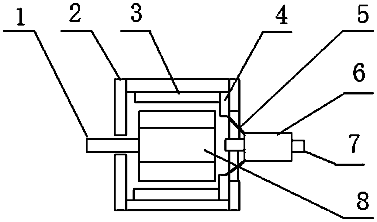
[0012] The present invention will be further described below in conjunction with the accompanying drawings and specific embodiments.

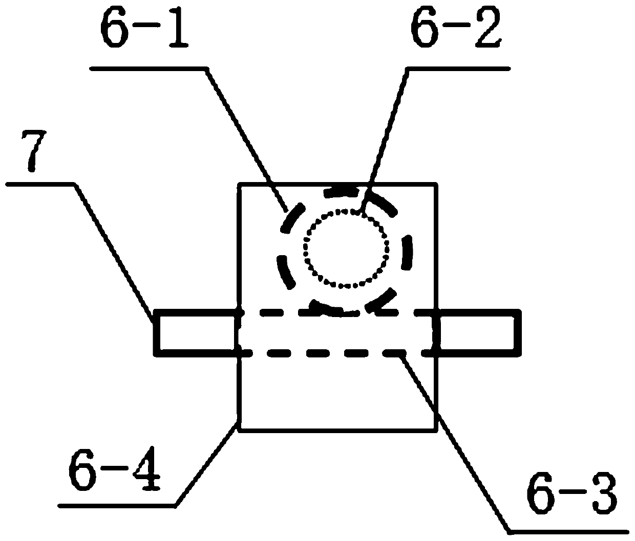
[0013] Refer to attached figure 1 And attached figure 2 , a permanent magnet generator with variable radial air gap, which includes a casing 2, a rotating shaft 1, a rotor permanent magnet 8, a stator winding 3, and also includes a fixed support shaft 7, an air gap adjustment drive mechanism 6, a slider 4 and The pull rod 5 and the rotor permanent magnet 8 are fixed on the rotating shaft 1. At the non-extending end of the motor, the fixed support shaft 7 is fixed with the end of the housing 2. The centerline of the fixed support shaft 7 is connected to the centerline of the rotating shaft 1. Coincidentally, the air gap adjustment drive mechanism 6 is movably connected to the fixed support shaft 7, and moves axially along the fixed support shaft 7, and the air gap adjustment drive mechanism 6 at the motor end and one end of two or more pull ro...


PUM


Abstract

The invention relates to a permanent magnet generator with variable radial air gap, comprising a shell, a rotating shaft, a stator winding, a fixed support shaft, an air gap adjustment drive mechanism, sliders, and pull rods. A rotor permanent magnet is fixed on the rotating shaft. At the non-extending end of a motor, the fixed support shaft and the end part of the shell are fixed together. The center line of the fixed support shaft overlaps with the center line of the rotating shaft. The air gap adjustment drive mechanism is movably connected to the fixed support shaft, and axially moves along the fixed support shaft. The air gap adjustment drive mechanism near the motor end is connected with one ends of the two or more pull rods, and the other ends of the pull rods are connected with the sliders fixed to the end part of the stator winding at the non-extending end. The two or more pull rods form an umbrella structure and move along with the air gap adjustment drive mechanism. The radial air gap between the stator winding and the rotor permanent magnet is changed through contraction of the pull rods like an umbrella, and the speed of the permanent magnet generator is changed through the change in radial air gap so as to change the output current of the generator.

Description

technical field [0001] The invention relates to the field of wind power generation, in particular to a permanent magnet generator with a variable radial air gap and a wind power generation device. Background technique [0002] At present, traditional adjustable air gap motors mainly include disc permanent magnet motors and squirrel cage motors. The disc permanent magnet motors with adjustable air gap adjust the axial air gap. Permanent magnet motors are difficult to manufacture and cost high, and are not suitable for wind power generation. There is also a squirrel-cage motor with a variable air gap. The spring of the air gap adjustment mechanism of the air gap squirrel cage motor is easily deformed, which affects the accuracy of the air gap adjustment, thereby affecting the performance of the motor. [0003] Wind power generation devices are mainly divided into two categories: doubly-fed permanent magnet generators with gearboxes and direct-drive permanent magnet generators...

Claims


Application Information

Patent Timeline
Patent Type & Authority Patents(China)
IPC IPC(8): H02K21/14H02K21/02H02J3/38F03D9/25H02P9/00H02P101/15
CPCH02J3/386H02K21/025H02K21/14H02P9/008H02P2101/15Y02E10/72Y02E10/76
Inventor 朱广辉夏云清柳微舒何娟杨智
Owner XIANGTAN ELECTRIC MFG CORP LTD
Why Eureka
Try Eureka