Pipeline rotary connector, cannon barrel direction adjusting mechanism and water cannon

A rotary connector and direction adjustment technology, which is applied in the direction of pipes/pipe joints/fittings, adjustable connections, weapon accessories, etc., can solve the problems that the rigid barrel cannot adjust the direction freely, and the elevation angle of the barrel cannot be adjusted, so as to reduce the sealing Sexual problems and the risk of screw loosening, improved life, and enhanced firmness

Active Publication Date: 2016-08-10
JIANGSU HENGDA POWER TECH DEV CO LTD
View PDF6 Cites 5 Cited by
  • Summary
  • Abstract
  • Description
  • Claims
  • Application Information

AI Technical Summary

Problems solved by technology

Therefore, the rigid gun barrel integrated with the water cannon tank usually cannot adjust the direction freely. When the

Method used


Image

  • Pipeline rotary connector, cannon barrel direction adjusting mechanism and water cannon
  • Pipeline rotary connector, cannon barrel direction adjusting mechanism and water cannon
  • Pipeline rotary connector, cannon barrel direction adjusting mechanism and water cannon

Examples


Embodiment 1

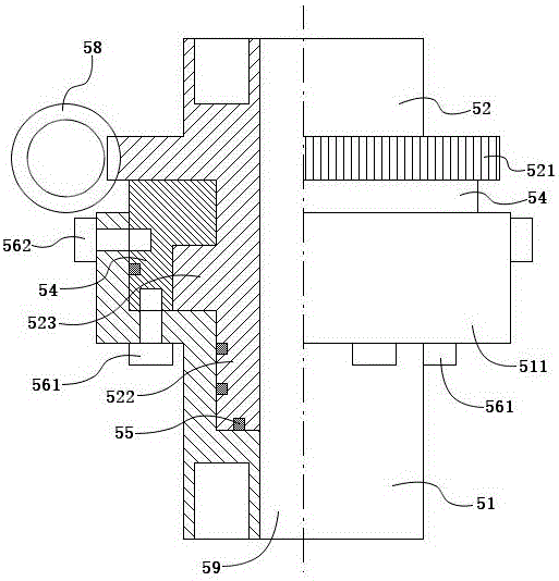
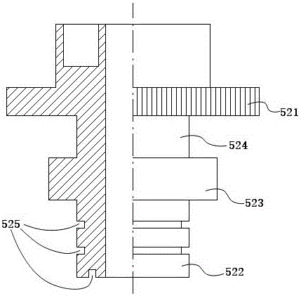
[0032] This embodiment is a pipe rotary connector, such as figure 1 , 2 , 3 and 4, including female joint 51, male joint 52, ring cover 54, worm rod 58 and motor. The female joint 51 and the male joint 52 are clamped together by a ring cover 54 , and a lumen 59 is provided inside. The female joint 51 and the male joint 52 can rotate around the axis of the lumen 59 .

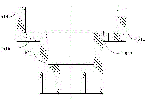
[0033] The female joint 51 is used to connect the fixed pipe, is installed at the end of the fixed pipe, and is provided with a first bayonet 512 and a second bayonet 513 . The first bayonet 512 and the second bayonet 513 have a cylindrical cavity, wherein the inner diameter of the first bayonet 512 is larger than the diameter of the lumen 59 . The inner diameter of the second bayonet 513 is larger than the inner diameter of the first bayonet 512 . The first bayonet 512 and the second bayonet 513 form a stepped bayonet structure. An opening is formed above the second bayonet opening 513 , and the opening is ...

Embodiment 2

[0042] This embodiment is a water cannon used for fire fighting or on a ship. The water cannon is provided with a barrel direction adjustment mechanism, and the barrel direction adjustment mechanism is realized by the pipe rotary connector in Embodiment 1. The water cannon is Figure 6 As shown, it includes a water cannon tank 1 , an air storage tank 41 , an air compressor 42 , a water storage tank 3 , a gun barrel 21 and a gun head 22 . The water cannon tank 1 is used to place the water that becomes the water cannon after launching, and is vertically installed on the ground or the base by the support frame 11. The air storage tank 41 is used for storing high-pressure compressed air and is connected with an air compressor 42 . The air compressor 42 compresses the air in the atmosphere to become high-pressure compressed air, which is sent into the air storage tank 41 through a pipeline. The air storage tank 41 is connected with the water cannon tank 1 through the solenoid val...


PUM


Abstract

The invention discloses a pipeline rotary connector, a cannon barrel direction adjusting mechanism and a water cannon. The water cannon is used for fire protection or naval vessels. The cannon barrel direction adjusting mechanism is arranged on the water cannon. The cannon barrel direction adjusting mechanism is realized through two pipeline rotary connectors mounted on a pipeline and is provided with a pipeline bending mechanism used for offsetting water flow lateral impact force. Each pipeline rotary connector comprises a female joint, a male joint, a ring cap, a worm and a motor, wherein the female joint and the male joint are clamped together through the ring cap, a pipeline cavity is formed in the female joint and the male joint, and the female joint and the male joint can rotate relatively. Each male joint is provided with a gear. Each worm and the corresponding motor are mounted on the corresponding female joint. Each motor can drive the corresponding male joint to rotate through the engagement function of an outer thread of the corresponding worm and the corresponding gear.

Description

technical field [0001] The invention relates to a water cannon for fire-fighting or ships, in particular to a direction adjustment mechanism for the cannon tube of the water cannon. Background technique [0002] Generally speaking, water cannons are divided into two types: the first is water cannons for fire fighting or ships; the second is water cannons for entertainment such as fountains. Under the prior art, the water cannon that fire-fighting is used or ship is used can not be called water cannon and must be called water cannon in fact. It fires water directly through the barrel through a high-power pump, and the fire is continuous. The main problems with this kind of water cannon are that one is that the range is not far enough, and the other is that the operating power is high. At present, the fire-fighting water cannon has a firing range of about 60 meters. In a fire scene, a distance of 60 meters may not be able to withstand the temperature of the flame, especiall...

Claims


Application Information

Patent Timeline
IPC IPC(8): A62C31/28F16L27/00A62C31/00F41G5/20F41G5/04
CPCA62C31/00A62C31/28F16L27/00F41G5/04F41G5/20
Inventor 戴国俊
Owner JIANGSU HENGDA POWER TECH DEV CO LTD
Why Eureka
Try Eureka