
Drive arrangement

A technology of driving device and transmission device, applied in the direction of transmission device, fluid transmission device, electromechanical device, etc., to achieve the effect of high cost, small external size, and shortened production interruption

Inactive Publication Date: 2016-08-10
FLENDER GMBH
View PDF9 Cites 0 Cited by
  • Summary
  • Abstract
  • Description
  • Claims
  • Application Information

AI Technical Summary

Problems solved by technology

The resulting maintenance time means lost production and is undesirable

Method used


Image

  • Drive arrangement
  • Drive arrangement
  • Drive arrangement

Examples


Embodiment Construction

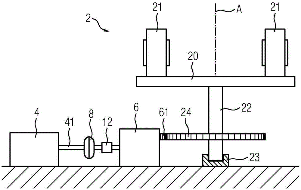
[0048] figure 1 A section through a drive for driving the vertical mill 2 is shown, wherein a torque transmission element 12 is arranged between the hydrodynamic clutch 8 and the vertical mill 2 .

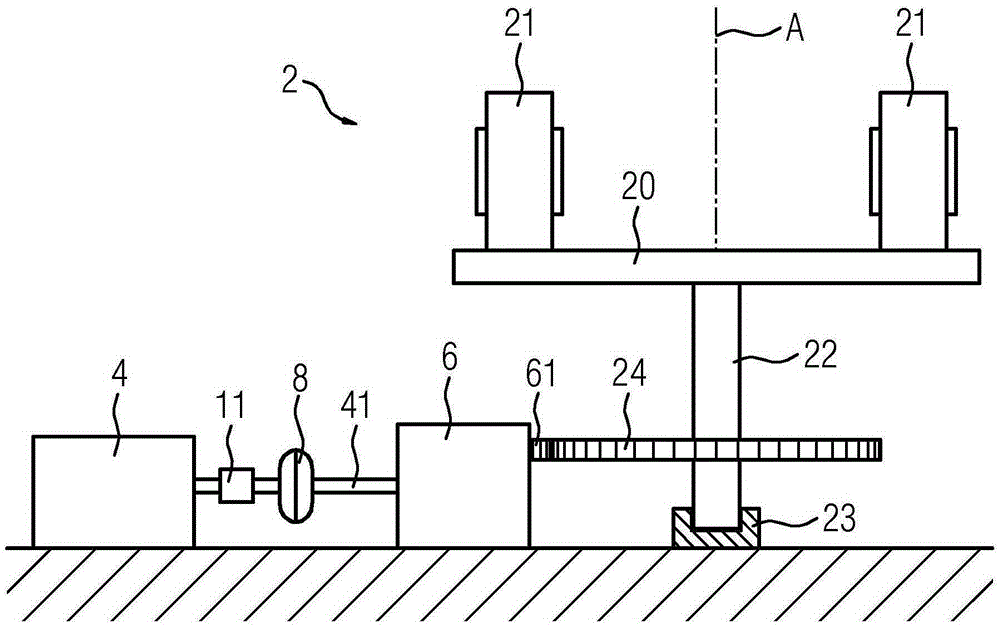
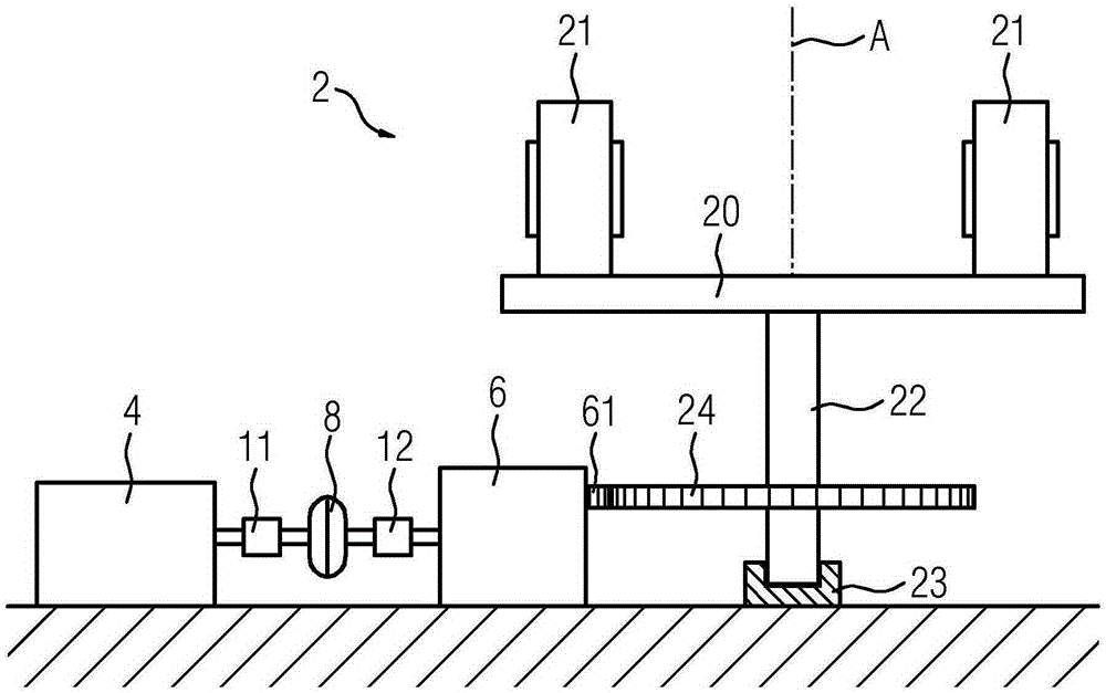
[0049] The vertical grinding machine 2 functioning as a working machine has a grinding disc 20 , which is rotatable about a vertical axis A of rotation. On the upper side of the grinding disc 20 a lining is formed, on which one or more grinding rollers 21 roll. The grinding disc is arranged in a rotationally fixed manner at the vertical upper end of a drive shaft 22 , which extends along the axis of rotation A, supported in an axial bearing 23 . A horizontally arranged crown 24 is arranged on the shaft 22 in a rotationally fixed manner below the grinding disc 20 . The drive device is used to drive the drive shaft 22 , the drive device includes the motor 4 , the transmission device 6 and the shaft 41 connecting the motor 4 with the transmission device 6 . The shaft 41 comprises a...


PUM


Abstract

A drive arrangement for driving a work machine (2) includes a motor (4) configured to generate a torque, and a transmission apparatus (41) configured to transmit the torque from the motor (4) to the work machine (2). The transmission apparatus (41) includes a fluid coupling and at least one controllable torque transmitter (10, 11) configured to control transmission of the torque from the motor (4) to the work machine (2).

Description

technical field [0001] The invention relates to a drive, in particular for a mill, and to a method for operating the drive. Background technique [0002] DE 202009016825 U1 (Gebr. Pfeiffer AG) of April 8, 2010 describes a mill comprising a housing, a milling disc with a lining and a milling roller rolling on the lining, wherein the milling roller is Can not be interfered in operation. The grinding machine also includes at least two drives with motors and transmissions, which drive the grinding discs. In order to be able to balance design-dependent or known selected differences in the properties of the drive, ie, the properties of the electric motor and the reduction gear, at least one transmission, preferably each transmission, is assigned a worm gear clutch. The torque characteristic curve of the turbine clutch is selected in such a way that the different characteristics of the drives are compensated for so that each drive drives the grinding disc with its rated power. ...

Claims


Application Information

Patent Timeline
Patent Type & Authority Applications(China)
IPC IPC(8): B02C15/00B02C23/00H02K7/10
CPCB02C15/007B02C23/00H02K7/10B02C15/006B02C2015/008F16D33/02F16D2300/0214F16D48/00F16H47/02
Inventor 安德烈亚斯·库贝
Owner FLENDER GMBH
Learn More