
Milling machine for sample collection and preparation

A powder milling machine and sample technology, which is applied in the preparation, sampling, and instrumentation of test samples, can solve the problems of high labor intensity in feeding operations, sample loss, and the jamming of rotary knives, so as to ensure the working efficiency of flour milling, Reduce the probability of being blocked and ensure the effect of work efficiency

Active Publication Date: 2019-03-05
HUNAN SUNDY SCI & TECH DEV
View PDF9 Cites 0 Cited by
  • Summary
  • Abstract
  • Description
  • Claims
  • Application Information

AI Technical Summary

Problems solved by technology

If the distance between the sieve and the rotary knife is small, no shearing force can be formed between the screen and the rotary knife, and the crushing and milling cannot be completed.
This makes the friction between the screen and the rotary knife larger, wears faster, and has a shorter service life
If the screen or rotary knife is not replaced in time, it will affect the milling effect and the final test accuracy of the sample, and if it is replaced frequently, the cost of use will increase and the work efficiency will be low
At the same time, this method of grinding and making powder may cause risks such as the jamming of the rotary knife and the burning of the motor when encountering large-grained samples.
[0006] 2. For samples with large internal water (such as coal samples), it is easy to block the screen during pulverization
However, the existing pulverizing device mainly relies on centrifugal force to throw the pulverized sample out of the sieve. Since the centrifugal force of the sample with a small internal particle size will also be very small, some coal samples will adhere to the vicinity of the sieve hole, and as time passes It will block the screen, so that the pulverized coal that has been crushed to the required particle size will continue to be crushed in the pulverizing chamber even if it is not screened out from the screen. The crushed coal sample will affect the final test accuracy of the sample; at the same time, when the screen If the net is blocked to a certain extent, it will make it impossible to complete the milling action
[0007] 3. Low sample collection rate
The existing pulverizing device mainly sucks the pulverized coal into the collection chamber for deposition through the high negative pressure system. Since the pulverized coal in the pulverizing chamber needs to be collected in this way, a relatively large negative pressure must be used for suction, and the negative pressure is another There will be an increased positive pressure in the filter device at one end, and a lot of over-broken coal powder inhaled will be discharged from the filter device, resulting in a low collection rate and affecting the final test results of the sample.
[0008] 4. There is still a contradiction between the easy blockage of the screen and the vulnerability of the screen in the existing milling device
Taking coal samples as an example, because the coal needs to be crushed to 0.2mm during the coal quality test, the hole of the screen must also be 0.2mm, which is very small. If the traditional straight hole screen is used, the thickness of the screen must be It needs to be kept within 0.2mm, otherwise the screen will be easily blocked and the discharge will not be smooth
However, the 0.2mm thick screen is easily punctured when it is impacted by coal particles during pulverization, which makes the service life of the screen short
[0009] 5. A large amount of dust or fine particles will be generated during the crushing process of the existing pulverizing device, which is easy to remain and adhere to the crushing tool and the inner wall of the crushing cavity, resulting in sample loss, which is not conducive to disassembly and cleaning, and this residual sample It will also affect the accuracy of the next sample preparation.
At the same time, the automation degree of the existing milling equipment is not high, and it is often necessary to manually switch between retaining and discarding samples, and the labor intensity of the feeding operation is high.

Method used


Image

  • Milling machine for sample collection and preparation
  • Milling machine for sample collection and preparation
  • Milling machine for sample collection and preparation

Examples


Embodiment Construction

[0037] The present invention will be further described in detail below in conjunction with the accompanying drawings and specific embodiments.

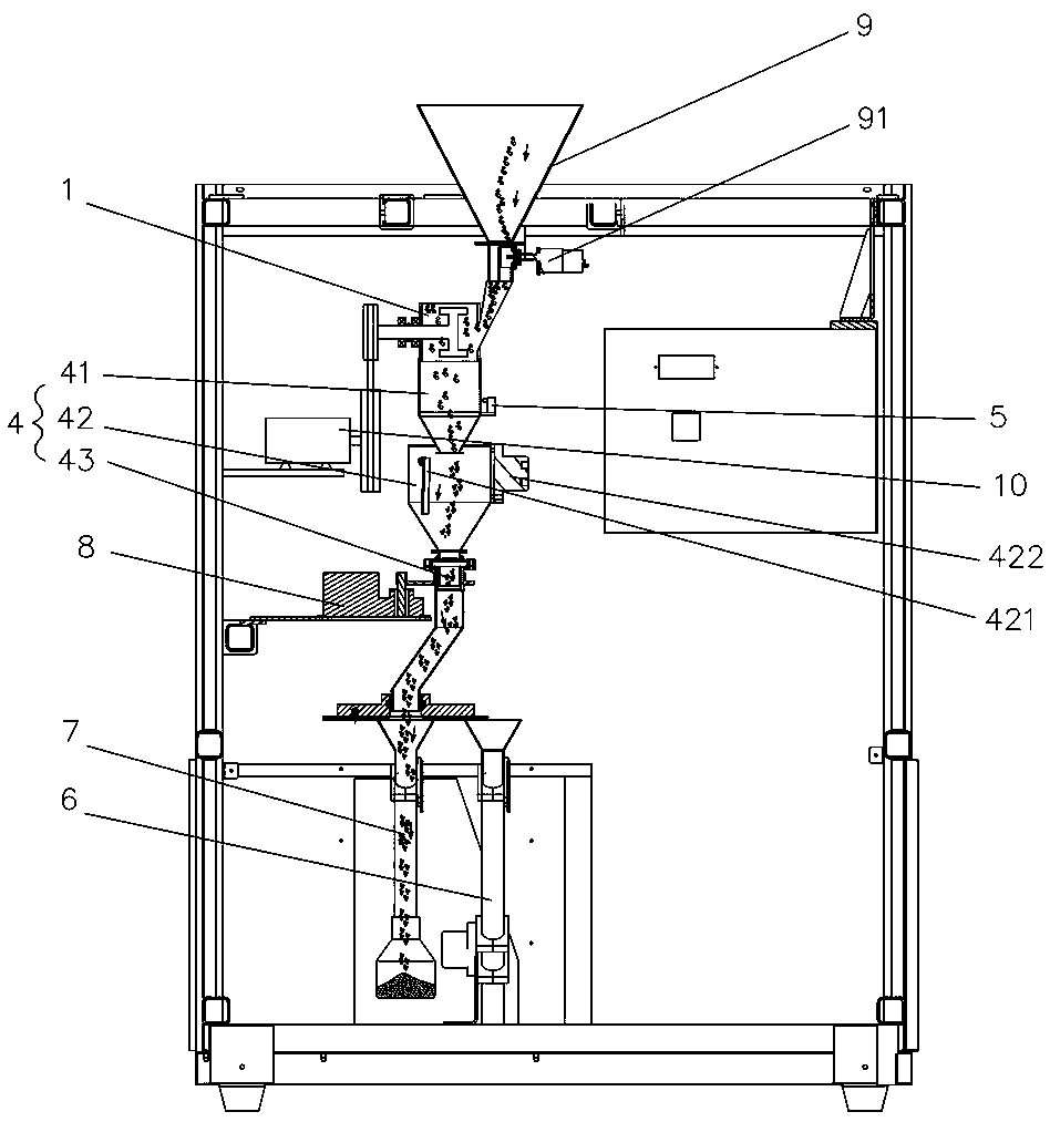
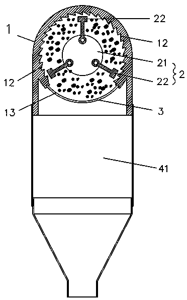
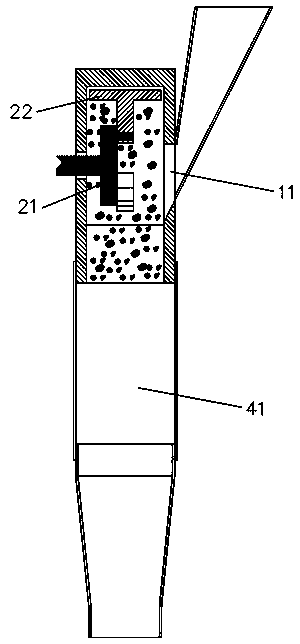
[0038] like Figure 1 to Figure 4 As shown, the present invention provides a kind of pulverizing machine for sample collection and processing, comprising a pulverizing chamber 1, which is provided with a material inlet 11, and is provided with a rotatable pulverizer in the pulverizing chamber 1. The powder rotary knife assembly 2 and the powder making chamber 1 are respectively provided with an annular crushing area 12 for pulverizing samples and an annular sieve area 13 for filtering samples on the inner circumferential surface of the powder making rotary knife assembly 2. The sieve area 13 is provided with an annular sieve 3 , and the milling rotary knife assembly 2 rotates at high speed in the milling chamber 1 and cooperates with the annular crushing area 12 to crush the samples and discharge them through the annular sieve 3 . Th...


PUM


Abstract

The invention discloses a flour mill for collecting and preparing samples. The flour mill comprises a flour milling cavity, wherein a feeding opening is formed in the flour milling cavity; a rotary flour-milling rotating blade assembly is arranged inside the flour milling cavity; an annular crushing area used for crushing samples and an annular sieve net area used for filtering samples are formed in the inner annular surface of the rotating circumference of the flour-milling rotating blade assembly in the flour milling cavity; the flour-milling rotating blade assembly rotates at high speed in the flour milling cavity and cooperates with the annular crushing area to collide and crush the samples and then discharge the samples through the annular sieve net. The flour mill has the advantages that the structure is simple and compact, the crushing and sample-preparing accuracy can be further improved, and the service life of the flour mill is prolonged.

Description

technical field [0001] The invention mainly relates to the field of sample collection and processing equipment, in particular to a powder making machine for sample collection and processing. Background technique [0002] For the sampling, sample preparation, and testing of material (such as ore, coal) samples, each country has mandatory standards, and the sampling and processing of samples must be carried out in accordance with the standards. The principle of sample sampling, sample preparation, and testing work process is to gradually reduce the particle size and quality of the collected samples without destroying the representativeness of the sample, until it meets the particle size and quality of the sample in the laboratory test ( Weight) accuracy requirements, and then carry out relevant laboratory analysis on the samples that meet the requirements. [0003] For example, taking coal sampling as an example, it is actually a sampling and analysis process. The purpose of ...

Claims


Application Information

Patent Timeline
Patent Type & Authority Patents(China)
IPC IPC(8): B02C18/14B02C18/18B02C18/16B02C23/08B02C23/16G01N1/28
CPCB02C18/143B02C18/16B02C18/184B02C23/08B02C23/16B02C2023/165G01N1/286
Inventor 张明庆
Owner HUNAN SUNDY SCI & TECH DEV
Learn More