Chamfering machine

A technology of chamfering machine and machine head, which is applied in the field of chamfering machines, can solve the problems that the processing of pipe sleeve products cannot be realized at one time, and achieve the effects of reducing manual processing, low production cost, and reasonable settings

Active Publication Date: 2018-06-19
东莞市精探电子科技有限公司
View PDF8 Cites 2 Cited by
  • Summary
  • Abstract
  • Description
  • Claims
  • Application Information

AI Technical Summary

Problems solved by technology

[0002] During the secondary processing of semi-finished products such as sleeves and needle tubes, local internal chamfering is required. The existing processing equipment has limitations and cannot realize the internal chamfering of the nozzles and sleeves of sleeves at one time.

Method used


Image

  • Chamfering machine
  • Chamfering machine

Examples


Embodiment Construction

[0013] In order to more clearly illustrate the technical solutions in the embodiments of the present invention or the prior art, the following will briefly introduce the drawings that need to be used in the description of the embodiments or the prior art. Obviously, the accompanying drawings in the following description are only These are some embodiments of the present invention. For those skilled in the art, other drawings can also be obtained according to these drawings without any creative effort.

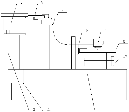
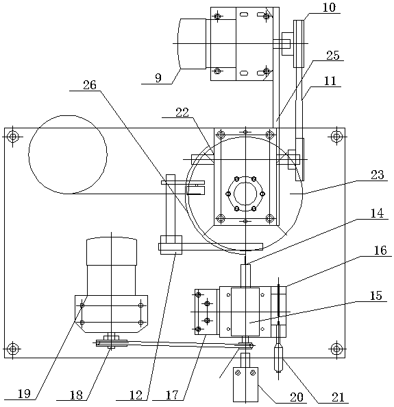
[0014] see as figure 1 —— figure 2 As shown, this specific embodiment adopts the following technical scheme: it includes a base 1, a stand 2, a vibrating plate 3, a separate blanking device 4, a first cylinder 5, a blanking funnel 6, a second cylinder 7, a working turntable 8, Speed ​​regulating motor 9, synchronous wheel 10, synchronous belt 11, bracket 12, cam 13, chamfering needle 14, machine head 15, XY axis moving slide 16, lifting slide 17, pulley 18, high-speed motor 1...


PUM


Abstract

The invention relates to the technical field of electronic testing and packaging processing equipment, in particular to a chamfering machine. A rack is provided with a vibrating disk which is connected with a split discharging device. A first air cylinder is connected to the split discharging device, and the split discharging machine is connected with a discharging hopper. The discharging hopper and a second air cylinder are arranged above a working rotary disk. A speed regulating motor is connected with synchronizing wheels. A synchronizing belt is arranged on the synchronizing wheels. A cam is arranged below the working rotary disk. A chamfering pin is arranged on one side of the working rotary disk. A machine head is connected with the chamfering pin and an X-axis and Y-axis mobile sliding table, and the X-axis and Y-axis mobile sliding table is connected with a lifting sliding table. A micro-drum regulating device is arranged on the X-axis and Y-axis mobile sliding table. The working rotary disk is provided with a discharging groove. An eight-station divider is arranged below the working rotary disk. By means of the chamfering machine, the limitation of existing processing equipment is overcome. Meanwhile, efficient mass production of products can be ensured, manual processing intensity is greatly reduced, and the chamfering machine is safe and intelligent.

Description

technical field [0001] The invention relates to the technical field of electronic testing and packaging processing equipment, in particular to a chamfering machine. Background technique [0002] During the secondary processing of semi-finished products such as sleeves and needle tubes, local internal chamfering is required. The existing processing equipment has limitations and cannot realize the internal chamfering of the nozzles and sleeves of sleeves at one time. Contents of the invention [0003] The object of the present invention is to provide a chamfering machine with simple structure, reasonable design and convenient use in view of the defects and deficiencies of the prior art. [0004] In order to achieve the above object, the technical solution adopted by the present invention is: it includes a base, a stand, a vibrating plate, a separate blanking device, a first cylinder, a blanking funnel, a second cylinder, a working turntable, a speed regulating motor, a synch...

Claims


Application Information

Patent Timeline
Patent Type & Authority Patents(China)
IPC IPC(8): B23D79/00
CPCB23D79/00
Inventor 茹仲明
Owner 东莞市精探电子科技有限公司
Why Eureka
Try Eureka