
Automated Spot Welding Process for Chainsaw Guide Plate

A technology of chainsaw guide plate and spot welding, applied in welding equipment, manufacturing tools, resistance welding equipment, etc., can solve the problems of low welding efficiency and achieve the effect of prolonging the service life

Active Publication Date: 2017-11-24
浙江辉煌三联实业股份有限公司
View PDF6 Cites 0 Cited by
  • Summary
  • Abstract
  • Description
  • Claims
  • Application Information

AI Technical Summary

Problems solved by technology

Although the rotary assembly line it adopts saves space compared with the linear assembly line, it requires the cooperation of multiple stations to complete the welding of all solder joints, and the welding efficiency is low

Method used


Image

  • Automated Spot Welding Process for Chainsaw Guide Plate
  • Automated Spot Welding Process for Chainsaw Guide Plate
  • Automated Spot Welding Process for Chainsaw Guide Plate

Examples


Embodiment Construction

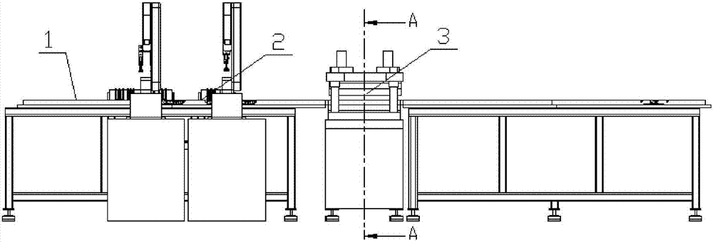
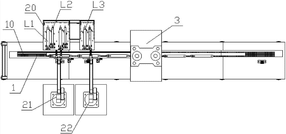
[0036] Such as figure 1 As shown, the chainsaw guide automatic spot welding equipment includes a frame, and a chain saw guide plate dislocation spot welding cycle feeding mechanism 1, a feeding device 2, a spot welding device 3, and a feeding device arranged on the frame.

[0037] Among them, such as Figure 2 to Figure 5 As shown, the circular feeding mechanism 1 for chainsaw guide plate dislocation spot welding includes a feeding guide rail 11 , a return guide rail 12 , and a dislocation spot welding guide rod 10 . The misplaced spot welding guide bar 10 is used for clamping the chain saw guide plate, and the chain saw guide plate is composed of the first chain saw guide plate, the second chain saw guide plate and the third chain saw guide plate welded side by side as a whole, so The first chainsaw guide plate, the second chainsaw guide plate, and the third chainsaw guide plate are stacked and positioned and clamped on the misplaced spot welding guide rod 10 and then spot w...


PUM


Abstract

The invention discloses an automatic spot welding technology for a chain saw guide plate. The automatic spot welding technology comprises following steps: step one, a dislocation spot welding guide rod enters an initial end of a feed guide rail from a terminal-point end of a return guide rail; step two, chain saw guide plate sheets constituting the chain saw guide plate are stacked on the dislocation spot welding guide rod by a loading device; step three, a spot welding device welds the chain saw guide plate sheets together to constitute the chain saw guide plate; step four, the dislocation spot welding guide rod and the welded chain saw guide plate are separated by an unloading device; step five, the dislocation spot welding guide rod is pushed to an initial end of the return guide rail from a terminal-point end of the feed guide rail; step six, the dislocation spot welding guide rod slides to the terminal-point end of the return guide rail from the initial end of the return guide rail and starts a new round of cycle. With the adoption of the automatic spot welding technology for the chain saw guide plate, all welding spots are welded once, so that the welding efficiency is greatly improved.

Description

technical field [0001] The invention relates to the processing technology of the chain saw guide plate, in particular to the spot welding technology of the chain saw guide plate. Background technique [0002] The traditional chain saw guide plate spot welding equipment adopts a rotary spot welding structure. The Chinese utility model patent with the publication number 203091956U disclosed a rotary spot welding machine for saw chains on July 31, 2013. It adopts a rotary Type multi-station design, a total of four directions can be positioned; the workpiece is fixed on the positioning mechanism at intervals of 90°. After the loading of the first processing position is completed, the turntable automatically turns to the second processing position, the welding torch group moves to complete the welding of part of the solder joints, the turntable turns to the third processing position for welding, completes the welding of part of the solder joints, and then turns to the fourth The...

Claims


Application Information

Patent Timeline
Patent Type & Authority Patents(China)
IPC IPC(8): B23K11/11B23K11/36
CPCB23K11/115B23K11/36
Inventor 赵志火
Owner 浙江辉煌三联实业股份有限公司
Learn More