Laser cutting chip mounter

A laser cutting and placement machine technology, which is applied in laser welding equipment, welding equipment, metal processing equipment, etc., can solve problems such as poor economy, deviation of placement position, damage to the physical structure of the camera substrate, etc.

Active Publication Date: 2016-08-10
江苏韵腾激光科技有限公司
View PDF8 Cites 5 Cited by
  • Summary
  • Abstract
  • Description
  • Claims
  • Application Information

AI Technical Summary

Problems solved by technology

[0002] With the development of social and economic life, cameras are widely used, but in the existing technology, the technology of cutting camera substrates is very backward, and the method of manual cutting is often used to cut the camera substrates, and then the cut substrates are manually pasted on high temperature. On the diaphragm, but the

Method used


Image

  • Laser cutting chip mounter
  • Laser cutting chip mounter

Examples


Embodiment Construction

[0018] In order to make the object, technical solution and advantages of the present invention clearer, the present invention will be further described in detail below in conjunction with the accompanying drawings and embodiments. It should be understood that the specific embodiments described here are only used to explain the present invention, not to limit the present invention.

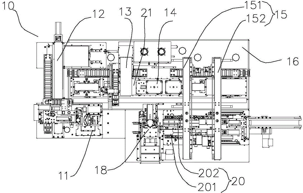
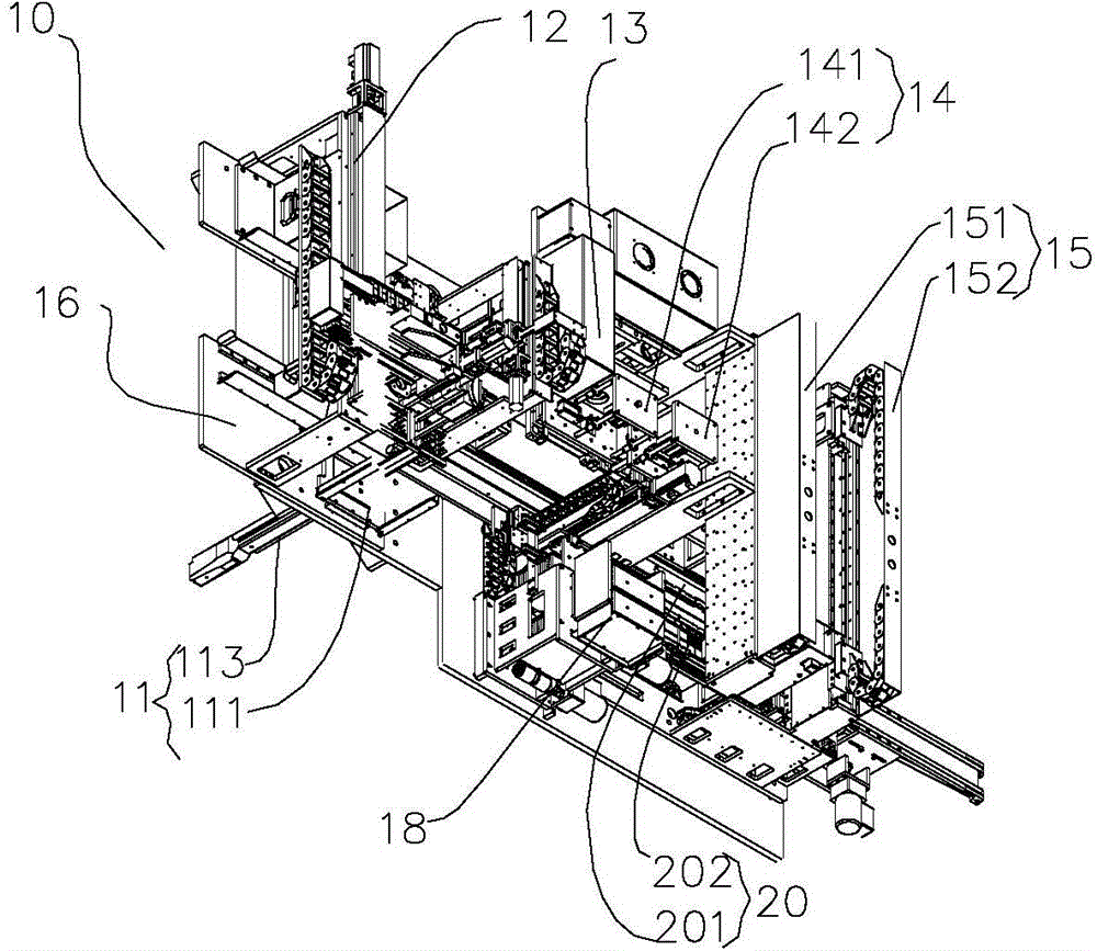
[0019] see figure 1 , figure 1 It is a structural schematic diagram of the laser cutting and placement machine of the present invention. In this embodiment, the laser cutting and placement machine 10 is used to cut the camera substrate and attach the cut substrate to the high temperature film, including a machine body 16, a container The control assembly placed in the machine body 16, the substrate feeding structure assembly 11 installed on the machine body 16, the substrate cutting and positioning assembly, the laser cutting mechanism 13 installed on the machine body 16 and cooperating with the s...


PUM


Abstract

The invention discloses a laser cutting chip mounter, comprising a machine body, a control assembly, a substrate feeding structure assembly, a substrate cutting positioning assembly, a laser cutting mechanism, at least two holders, a holder conveying mechanism, a substrate feeding and blanking translation mechanism, a high temperature membrane feeding structure assembly, a membrane mounting mechanism assembly, a high temperature membrane feeding and blanking translation mechanism, and a holder exchange mechanism. The laser cutting mechanism comprises a laser generator, an optical path structure, and a cutting structure. The holder is arranged on the holder conveying mechanism. The holder conveying mechanism can drive the holder to move back and forth on a Y-axis relative to the machine body. The laser cutting chip mounter is high in working efficiency, and can accurately adjust positions of all directions of a to-be-cut camera substrate, and is high in precision, and operates in a full automatic manner. The laser cutting chip mounter accurately positions the cutting position of a camera substrate, and the cut camera substrate is even and beautiful, and the substrate can be accurately mounted on a high temperature membrane. Chip-mounting effect is good, and adaptability is good.

Description

technical field [0001] The invention relates to the technical field of laser cutting and placement, in particular to a laser cutting placement machine. Background technique [0002] With the development of social and economic life, cameras are widely used, but in the existing technology, the technology of cutting camera substrates is very backward, and the method of manual cutting is often used to cut the camera substrates, and then the cut substrates are manually pasted on high temperature. On the diaphragm, but the method of manually cutting the camera substrate and the patch is inefficient, high in cost, and poor in economy, and due to the instability of manual operation, the cutting operation has a high error rate, and it is easy to damage the camera substrate during the cutting process. There are deviations in the physical structure and the position of the patch. [0003] Therefore, those skilled in the art have been devoting themselves to developing a high-efficiency,...

Claims


Application Information

Patent Timeline
IPC IPC(8): B23K26/38B23K26/70
Inventor 邹武兵张德安张波郑军伟梁剑金
Owner 江苏韵腾激光科技有限公司
Why Eureka
Try Eureka