Welding positioning device for mixed-flow runner blade and its positioning measurement method

A runner blade, welding positioning technology, applied in auxiliary devices, welding equipment, auxiliary welding equipment and other directions, can solve problems such as unsatisfactory positioning effect and complex structure

Active Publication Date: 2017-12-22
HANGZHOU RESOURCE POWER EQUIP
View PDF9 Cites 0 Cited by
  • Summary
  • Abstract
  • Description
  • Claims
  • Application Information

AI Technical Summary

Problems solved by technology

This structure is relatively complex, and the positioning effect is not ideal

Method used


Image

  • Welding positioning device for mixed-flow runner blade and its positioning measurement method
  • Welding positioning device for mixed-flow runner blade and its positioning measurement method
  • Welding positioning device for mixed-flow runner blade and its positioning measurement method

Examples


Embodiment 1

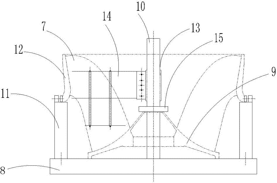
[0047] Embodiment 1: as figure 1 , figure 2 , image 3 with Figure 4 As shown, a welding positioning device for a mixed-flow runner blade includes a runner blade 7 and a bottom plate 8, the bottom plate 8 is provided with a runner upper crown 9, and the runner upper crown 9 passes through the pillar 10 is fixed with the base plate 8, and the two ends of the upper part of the base plate 8 are respectively provided with adjustable lower ring supports 11, and the upper part of the adjustable lower ring support 11 is provided with a runner lower ring 12, and the described rotary The bottom end of the runner blade 7 is fixed to the upper crown 9 of the runner, and the upper end of the runner blade 7 is in movable contact with the runner lower ring 12;

[0048] The support 10 is covered with a rotating shaft 13, and the rotating shaft 13 drives the blade shape line model group 14 to rotate, and the blade shape line model group 14 is positioned with the runner blade 7;

[0049]...

Embodiment 2

[0078] Embodiment 2: the positioning measuring method of the welding positioning device of mixed-flow runner blade, according to the following steps:

[0079] (1) Analysis:

[0080] Use the positioning device to achieve precise positioning of the blade, use a three-dimensional measuring instrument to measure the cross-section of the blade, and match the three-dimensional measured results of the runner blade with the theoretical value in the three-dimensional CAD software, and judge whether the blade installation position is accurate according to the deviation between the two;

[0081] (2), positioning operation:

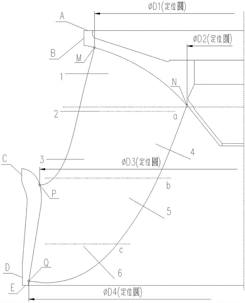
[0082] 1. Design and determine the measurement section and positioning model section, the sections are 1, 2, 3, 4, 5 and 6 sections, the positioning model sections are a, b and c, and the processing runner blades Make points according to the cross-section, that is, locate the reference point, and each cross-section has 3 points;

[0083] According to the diameter o...

Embodiment 3

[0105] Embodiment 3: The positioning measurement method of the welding positioning device of the Francis runner blade, according to the following steps:

[0106] (1) Analysis:

[0107] Use the positioning device to achieve precise positioning of the blade, use a three-dimensional measuring instrument to measure the cross-section of the blade, and match the three-dimensional measured results of the runner blade with the theoretical value in the three-dimensional CAD software, and judge whether the blade installation position is accurate according to the deviation between the two;

[0108] (2), positioning operation:

[0109] 1. Design and determine the measurement section and positioning model section, the sections are 1, 2, 3, 4, 5 and 6 sections, the positioning model sections are a, b and c, and the processing runner blades Make points according to the cross-section, that is, locate the reference point, and each cross-section has 2 points;

[0110] According to the diamete...


PUM


Abstract

The invention relates to a positioning device, in particular to a welding positioning device for francis turbine runner vanes and a positioning measuring method thereof. The device comprises a runner vane and further comprises a bottom plate, wherein a runner crown is arranged in the bottom plate, the runner crown is fixed with the bottom plate by a strut, adjustable lower ring supports are respectively arranged at two ends of the upper part of the bottom plate, a runner lower ring is arranged at the upper part of the adjustable lower ring support, the bottom end of the runner vane is fixed with the runner upper crown, and the upper end of the runner vane is in movable contact with the runner lower ring. The welding positioning device for francis turbine runner vanes and the positioning measuring method thereof are compact in structure, simple and convenient to operate and high in use performances.

Description

technical field [0001] The invention relates to a positioning device, in particular to a welding positioning device for mixed-flow runner blades and a positioning measurement method thereof. Background technique [0002] The Francis turbine runner is the core component of the Francis turbine. The installation and positioning of the runner blades has high requirements, and its positioning accuracy directly affects the hydraulic performance, stability, and other core parameters of the runner. [0003] After the runner blades are installed, it is required to check parameters such as the inlet pitch, outlet opening, and inlet and outlet angles of the runner to ensure the accuracy of the installation position. [0004] However, due to the particularity of the blade shape of the Francis turbine runner, it is difficult to guarantee the installation and measurement accuracy by using general tools. [0005] Chinese patent 201320731467.4 discloses a large runner blade vertical proces...

Claims


Application Information

Patent Timeline
Patent Type & Authority Patents(China)
IPC IPC(8): B23K37/04
CPCB23K37/04
Inventor 李贵智
Owner HANGZHOU RESOURCE POWER EQUIP
Why Eureka
Try Eureka