
A brick automatic production line

An automatic production line and brick forming technology, applied in the direction of supply device, ceramic forming machine, forming conveyor, etc., can solve the problems of easy failure, position error, large structure area, etc.

Active Publication Date: 2018-07-03
福建省东方水泥制品有限公司
View PDF8 Cites 0 Cited by
  • Summary
  • Abstract
  • Description
  • Claims
  • Application Information

AI Technical Summary

Problems solved by technology

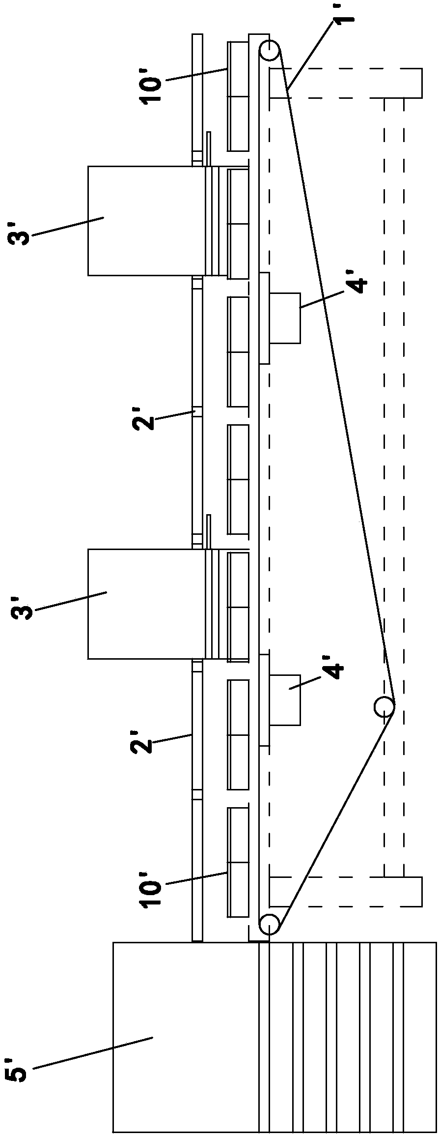
[0004] A kind of automatic brick production line in the above-mentioned prior art has the following problems in the manufacture and actual use of the equipment: 1. As disclosed in the above-mentioned Chinese patent application, the brick forming molds in the current production line are usually in the field The font is placed, that is, four brick forming molds are placed in a group to perform blanking and forming at the same time. The above positioning device prevents each group of brick forming molds from advancing with the operation of the conveyor belt through the lowering of the gear bar. The positioning of this method is After running for a period of time, the operation of the conveyor belt and the lifting action of the positioning device will gradually produce positional errors. In addition, the placement of the brick forming mold cannot be placed in the corresponding position every time, which will also increase the positional error, which may lead to It is impossible to position each group of brick forming molds when the bar is lowered, and it may even be stuck on the upper edge of the brick forming mold when the bar is lowered. If the position of the brick forming mold cannot be correctly positioned, the material will be misplaced when cutting. , which will directly affect the quality of colored brick molding, and the positioning device only blocks and locates in front of the advancing direction of each group of brick forming molds, and there is no limited position on both sides, which will also lead to a lateral offset The position will also lead to the dislocation of the blanking. In addition, the existing positioning device has a large mechanical structure, and the structure of the frame and rod is complicated, and it is prone to failure; The discharge hole, material storage hole and discharge hole in the blanking device should be set up in four groups corresponding to the four brick forming molds, and the discharge hole, material storage hole and discharge hole in the blanking device are circular holes. , to achieve the ratio of the amount of blanking, usually four circular holes are arranged in each group, and each group must be set within the range of a brick forming mold, and the gap between the discharge hole, the filling hole and the blanking hole must be made Corresponding and staggered positional relationship requirements, such a circular hole setting layout is very limited, if you want to increase the amount of cutting, you need to increase the diameter of each hole, because the position is cramped to meet the above requirements, it is difficult to make adjustments, a slight adjustment It may make it impossible for the filling hole to realize the completely staggered positional relationship with the discharging hole and the feeding hole during the movement, so that there will be no quantitative amount of feeding and material leakage, which will affect the color of the colored bricks. Quality requirements and waste of materials; 3. Whether it is the slurry of the pigment layer or the slurry of the concrete layer, there will be some dripping after each cutting. It is more troublesome on the edge of the brick or on the conveyor belt. If the dripping on the edge of the brick forming mold is not disposed of in time, the slurry in the brick forming mold may be connected together, so that the formed colored brick is unqualified and returned. It needs to be treated, if it drips on the conveyor belt, if it is not treated in time, it will condense into lumps on the conveyor belt, forming many lumps on the surface of the conveyor belt, and the uneven surface will affect the placement of the front brick forming mold and the subsequent slurry The vibration is flat, which will eventually affect the quality of colored brick molding

Method used


Image

  • A brick automatic production line
  • A brick automatic production line
  • A brick automatic production line

Examples


Embodiment Construction

[0034] In order to further explain the technical solution of the present invention, the present invention will be described in detail below through specific examples.

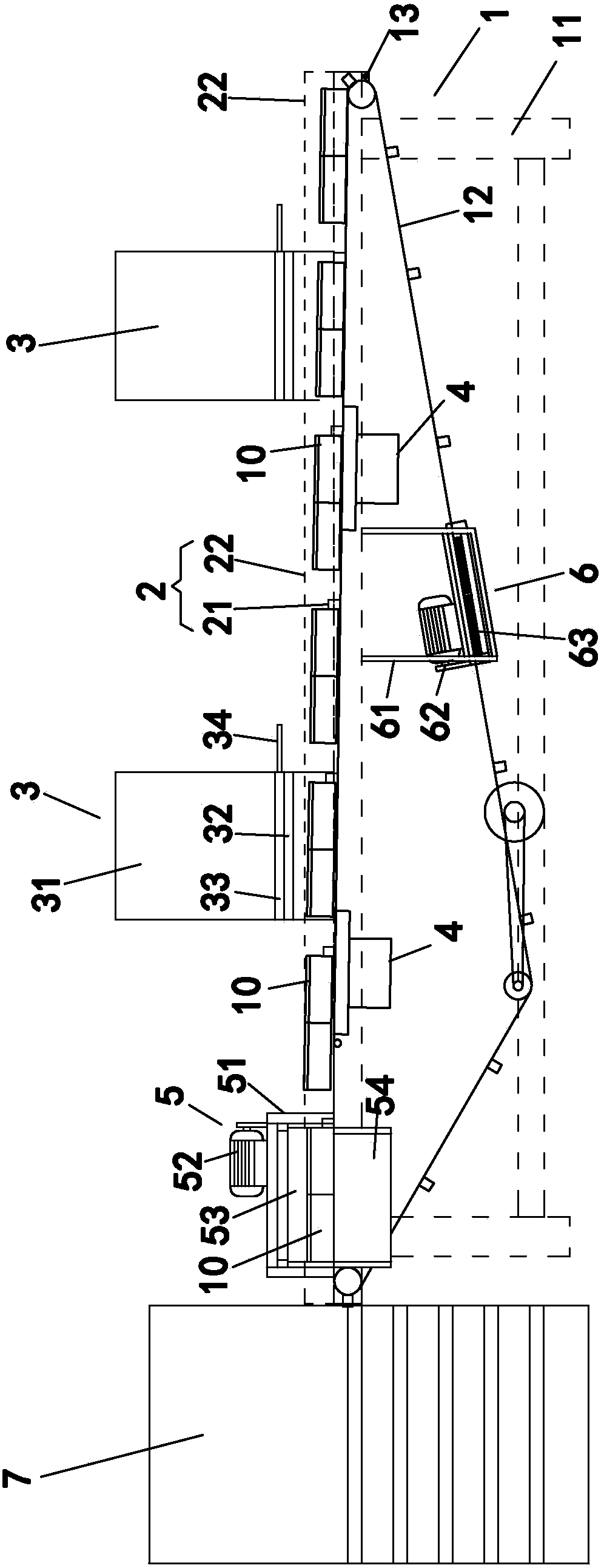
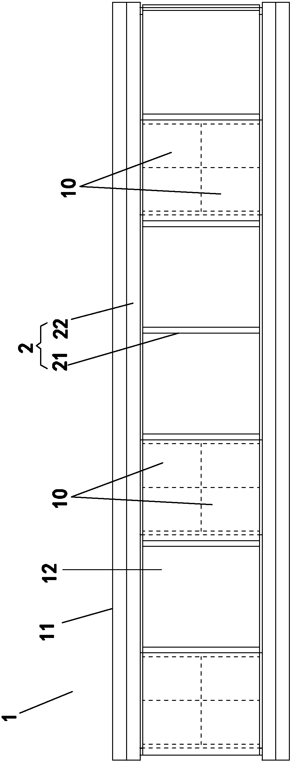
[0035] Such as figure 2 The disclosed automatic brick production line includes a conveying device 1 for conveying the brick forming mold 10, a positioning device 2 for positioning the blanking position of the brick forming mold 10, a blanking device 3 for blanking during conveying and positioning, and a conveyor The vibration device 4 on the device 1 is used to vibrate the charged brick forming mold 10 to spread the slurry evenly. It is installed at the output end of the conveying device 1 to arrange and stack the brick forming mold 10 for subsequent solidification and forming The output stacking device 7.

[0036] The conveying device 1 includes a frame 11, a conveyor belt 12 wound around the frame 11, and a transmission mechanism arranged on the frame 11 to drive the conveyor belt 12 to run. The transmissio...


PUM


Abstract

The invention discloses an automatic brick production line. By means of the automatic brick production line, stability and reliability of production and operation of the automatic brick production line are improved. The automatic brick production line comprises a conveying device used for conveying brick molds, a positioning device and a discharging device. The conveying device comprises a machine frame, a conveying caterpillar band and a transmission mechanism. The discharging device comprises a material barrel, a discharging baffle and a quantitative discharging gate plate. Material outlet holes are formed in the bottom of the material barrel. Discharging holes are formed in the discharging baffle. Material containing holes are formed in the quantitative discharging gate plate. According to the positioning device, block strips are arranged on the conveying caterpillar band, the conveying caterpillar band inclines so that the brick molds can lean on the block strips, the plurality of block strips are evenly distributed in the length direction of the conveying caterpillar band at fixed intervals, a variable frequency motor is adopted as a power source in the transmission mechanism, and the brick molds during conveying can be accurately and correspondingly arranged below the discharging device by controlling the working frequency of the variable frequency motor.

Description

technical field [0001] The invention relates to the field of brick production lines, in particular to an automatic production line of cast-molded bricks. Background technique [0002] Casting bricks are usually poured concrete, commonly used to produce pavement bricks or foam bricks, etc., the following is an example of pavement bricks, the main body of which is made of concrete pouring, used for pavement laying, and the upper surface layer is usually colored Pigment layer, this kind is also called colored brick. [0003] The production of colored bricks is now mostly an automated production line, and the current production line equipment has a general structure as follows figure 1 As shown, it includes a conveying device 1' for conveying the brick forming mold 10', a positioning device 2' for positioning the blanking position of the brick forming mold 10', a blanking device 3' for blanking during conveying and positioning, and is arranged on the conveying device 1 The vib...

Claims


Application Information

Patent Timeline
Patent Type & Authority Patents(China)
IPC IPC(8): B28B5/02B28B1/087B28B13/02B28B11/22
CPCB28B1/087B28B5/022B28B11/22B28B13/022B28B13/0295
Inventor 卢育文卢聪伟
Owner 福建省东方水泥制品有限公司
Learn More