Optical imaging anti-fake element

An anti-counterfeiting component and optical imaging technology, applied in the direction of printing and information-carrying cards, can solve the problems of inability to form, can not have multiple functions of anti-counterfeiting and packaging, and achieve the effect of reasonable structure and marking effect.

Inactive Publication Date: 2016-08-10
JIANGYIN TONGLI OPTOELECTRONICS TECH
View PDF16 Cites 7 Cited by
  • Summary
  • Abstract
  • Description
  • Claims
  • Application Information

AI Technical Summary

Problems solved by technology

But because the required micro-text structure is very fine (about several microns), and the limit printing stroke of general printing technology is more than 20 microns, the micro-text array and the microlens array of card and banknote in the prior art are all full board distribution
The optical units distributed all over the board only meet the anti-counterfeiting requirements, and cannot form the pattern logo of the size and size on the conventional product packaging, so it cannot appear as a commodity packaging material, that is, it cannot have multiple functions of anti-counterfeiting and packaging

Method used


Image

  • Optical imaging anti-fake element
  • Optical imaging anti-fake element
  • Optical imaging anti-fake element

Examples


Embodiment 1

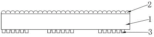
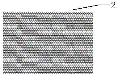
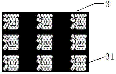
[0031] Such as Figure 1 to Figure 3 As shown, the optical imaging anti-counterfeiting element of Example 1 includes a substrate 1, which has a first surface and a second surface opposite to each other. The first surface is provided with a microlens layer 2 and the second surface is provided with a micro-image The text layer 3, the microlens units of the microlens layer 2 are distributed on the first surface, and the micrographic layer 3 is provided with a full-plate pattern 31 of the micrographic layer units. The picture in the micro-figure text layer in the attached drawing is a unit, taking the lowercase "a" as an example, making the unit full board pattern of the Chinese character "酒". figure 2 The full "a" in the word "酒" in the middle, and the black part other than the word "酒" are the blank areas of the miniature text layer.

[0032] The optical dynamic display effect of Embodiment 1 is specifically: the blank area and the microlens layer have no optical imaging dynamic e...

Embodiment 2

[0034] Such as Figure 4 As shown, the difference between the second embodiment and the first embodiment is that the thumbnail text layer 3 is provided with a blank pattern 32 of the thumbnail text layer unit. image 3 The black "wine" is used as the cell blank pattern, and the graphic area around the cell blank pattern is filled with "a".

[0035] The optical dynamic display effect of Embodiment 2 is specifically: the area "wine" where the blank pattern of the unit matches the microlens layer has no dynamic optical imaging effect.

Embodiment 3

[0037] Such as Figure 5 with 6 As shown, the difference between Embodiment 3 and Embodiment 1 is that the graphic units of the micro-graphics layer 3 are fully distributed on the second surface, and the micro-lens layer 2 is provided with a full-plate pattern 21 of micro-lens layer units. Figure 4 The microlenses in the outline of the word "wine" are arranged all over the board, and the non-"wine" part is a black area.

[0038] The optical dynamic display effect of the third embodiment is specifically: the non-"wine" part has no lens structure, and there is no optical imaging dynamic effect when matched with the micro-graphic layer.


PUM


Abstract

The invention discloses an optical imaging anti-fake element. The optical imaging anti-fake element comprises a base material, wherein the base material is provided with a first surface and a second surface which are opposite; a micro lens layer is arranged on the first surface; a miniature image-text layer is arranged on the second surface; and micro lens units of the micro lens layer or image-text units of the miniature image-text layer are arranged to form a unit full-plate pattern or a unit blank pattern. The optical imaging anti-fake element is reasonable in structure; the micro lens units of the micro lens layer or the image-text units of the miniature image-text layer are arranged to form the unit full-plate pattern or the unit blank pattern, so that the anti-fake element with a predetermined identifier is formed on the surface of the base material; and the anti-fake element has an anti-fake function, can be used as a packaging material, and has the identifier effect. The invention further discloses an application of the optical imaging anti-fake element.

Description

Technical field [0001] The invention relates to the field of optical imaging anti-counterfeiting technology, in particular to an optical imaging anti-counterfeiting element and its application. Background technique [0002] CN101563640, CN101443692, CN101120139, CN101346244, US5712731, US0034082, US4765656, US4892336, CN1271106, CN1552589 and other patent documents disclose the same type of anti-counterfeiting element with a microlens array and a micrograph array on both surfaces of the substrate, Among them, the micro-graphics array is located near the focal plane of the micro-lens array, and a pattern with a certain depth of field or a dynamic effect is reproduced by the moiré magnification effect of the micro-graphics array by the micro-lens array. [0003] At present, the use of moiré magnified patterns to achieve anti-counterfeiting effects is mostly used in high-security or high-value-added printed matter such as cards and cards, and has achieved very good results. However, ...

Claims


Application Information

Patent Timeline
Patent Type & Authority Applications(China)
IPC IPC(8): B42D25/21B42D25/305
CPCB42D25/21B42D25/305
Inventor 周永南冯煜
Owner JIANGYIN TONGLI OPTOELECTRONICS TECH
Why Eureka
Try Eureka