
Novel vehicle-mounted vibration and radiation headrest surrounding sound system

A sound system and radiating head technology, applied in vehicle seats, vehicle parts, special positions of vehicles, etc., can solve problems such as affecting passengers, reducing driving safety, and discounting aesthetics, so as to improve listening enjoyment and improve safety. , the effect of reducing costs

Active Publication Date: 2016-08-10
BESTAR HLDG
View PDF5 Cites 6 Cited by
  • Summary
  • Abstract
  • Description
  • Claims
  • Application Information

AI Technical Summary

Problems solved by technology

[0002] At present, the audio systems of conventional cars on the market are all used with traditional tweeters and woofers, and the existing car audio systems are generally installed in the car door leaves, center consoles, etc. Therefore, traditional car audio brings volume Large size, high cost, high space occupation, etc.
In the actual use of the car, there is often not only one person in the car. Therefore, when a person wants to listen to music, everyone in the car can hear it, which will affect the passengers who need to be quiet.
In order to solve this technical problem, the method adopted at present is to hide the car audio system somewhere in the car, such as a car audio seat disclosed in the Chinese Utility Model Patent (Patent No. 200920304855.8). It is: including a backrest and a headrest arranged on the upper end of the backrest, the headrest is composed of an internal bracket and an outer cover, two side wings are symmetrically arranged at the ends of both sides of the headrest, and a loudspeaker is fixedly arranged inside the side wings, The side wings can swing horizontally or vertically, and the speakers are arranged in the two side wings on both sides of the headrest. Although the occupancy of the interior space can be reduced to a certain extent, setting them on both sides of the headrest will firstly destroy the overall aesthetics of the seat. The feature is that the aesthetics are greatly reduced. Second, the safety of driving is also greatly reduced. Once an impact occurs, the speakers are easily damaged and easily hurt the passengers in the car. Third, there are only ordinary speakers in the side wings, and the sound effect is poor. Can be used alone, but does not provide high-quality listening enjoyment

Method used


Image

  • Novel vehicle-mounted vibration and radiation headrest surrounding sound system
  • Novel vehicle-mounted vibration and radiation headrest surrounding sound system
  • Novel vehicle-mounted vibration and radiation headrest surrounding sound system

Examples


Embodiment 1

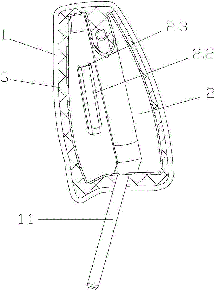
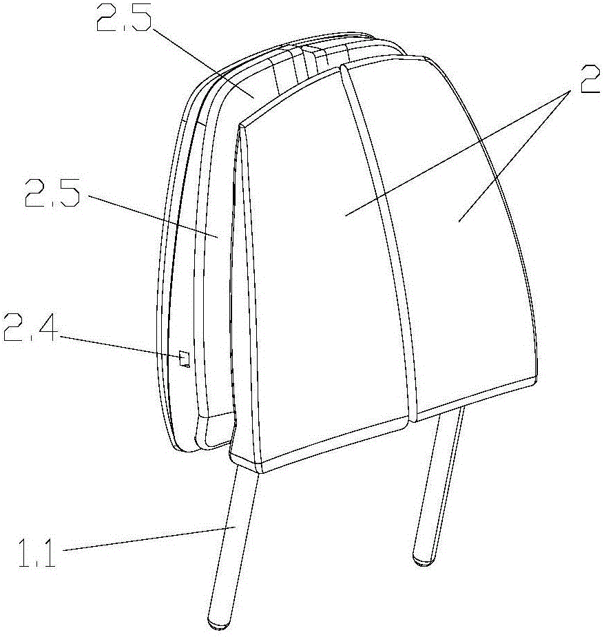
[0034] Embodiment 1: as figure 1 , figure 2 The new vehicle-mounted vibration radiation headrest surround sound system shown includes a headrest body 1, which is a general car seat headrest. The headrest body 1 is provided with two resonance boxes 2 that can produce resonance sound effects. , two resonance boxes 2 are arranged on the left and right sides inside the headrest body 1, and the two resonance boxes 2 are left-right symmetrical about the center of the headrest body 2, and foam is filled between the resonance box 2 and the headrest body 1 6. The foam 6 covers the resonance box 2, the headrest body 1 wraps the foam 6, the foam 6 keeps the resonance box 2 from the headrest body 1, and the two resonance boxes 2 do not touch .

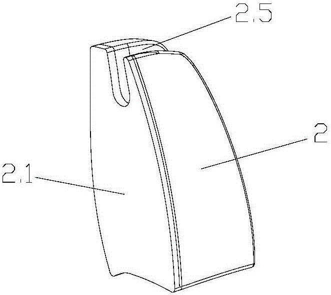
[0035] Such as 3, Figure 4 As shown, the vertical surface of the resonant box 2 is a flat radiation panel 2.1, and the inner wall of the radiation panel 2.1 is provided with a resonance source. At the lower position, the side of the exciter ...

Embodiment 2

[0039] Embodiment 2: refer to figure 1 , figure 2 The new vehicle-mounted vibration radiation headrest surround sound system shown includes a headrest body 1, which is a general car seat headrest. The headrest body 1 is provided with two resonance boxes 2, two resonance boxes The body 2 is arranged on the left and right sides inside the headrest body 1, and the two resonant boxes 2 are left and right symmetrical about the center of the headrest body 2, and the foam 6 is filled between the resonance box 2 and the headrest body 1, and the foam 6 Covering the resonance box 2, the headrest body 1 is wrapped with foam 6, and the foam 6 prevents the resonance box 2 from contacting the headrest body 1, and the two resonance boxes 2 from contacting each other.

[0040] Refer to 3, Figure 4 As shown, the vertical surface of the resonant box 2 is a flat radiation panel 2.1, and the inner wall of the radiation panel 2.1 is provided with a resonance source. At the lower position, the...

Embodiment 3

[0044] Embodiment 3: refer to figure 1 , figure 2 The new vehicle-mounted vibration radiation headrest surround sound system shown includes a headrest body 1, which is a general car seat headrest. The headrest body 1 is provided with two resonance boxes 2, two resonance boxes The body 2 is arranged on the left and right sides inside the headrest body 1, and the two resonant boxes 2 are left and right symmetrical about the center of the headrest body 2, and the foam 6 is filled between the resonance box 2 and the headrest body 1, and the foam 6 Covering the resonance box 2, the headrest body 1 is wrapped with foam 6, and the foam 6 prevents the resonance box 2 from contacting the headrest body 1, and the two resonance boxes 2 from contacting each other.

[0045] Refer to 3, Figure 4 As shown, the vertical surface of the resonant box 2 is a flat radiation panel 2.1, and the inner wall of the radiation panel 2.1 is provided with a resonance source. At the lower position, the...


PUM


Abstract

The invention belongs to the technical field of automobile parts and particularly relates to a novel vehicle-mounted vibration and radiation headrest surrounding sound system. At least one resonance box capable of making sounds is arranged in a headrest body. The space between the resonance boxes and the headrest body is filled with filler. The resonance boxes are embedded in the headrest body, make sounds independently and have a good low-frequency sound effect.

Description

technical field [0001] The invention belongs to the technical field of automobile parts, and in particular relates to a novel vehicle-mounted vibration radiation headrest surround sound system. Background technique [0002] At present, the audio systems of conventional cars on the market are all used with traditional tweeters and woofers, and the existing car audio systems are generally installed in the car door leaves, center consoles, etc. Therefore, traditional car audio brings volume Large size, high cost, and high space occupation. In the actual use of the car, there is often not only one person in the car. Therefore, when a person wants to listen to music, all the people in the car can hear it, which will affect the passengers who need to be quiet. In order to solve this technical problem, the method adopted at present is to hide the car audio system somewhere in the car, such as a car audio seat disclosed in the Chinese Utility Model Patent (Patent No. 200920304855.8...

Claims


Application Information

Patent Timeline
IPC IPC(8): B60N2/48H04R1/20
CPCB60N2/879H04R1/20
Inventor 王平李红元葛斌
Owner BESTAR HLDG
Learn More