Truss type multi-cavity steel plate shear wall and operation method thereof
A steel plate shear wall, multi-cavity technology, applied in the direction of walls, building components, buildings, etc., can solve the problems of complex structure, low operational flexibility, poor adaptability, etc.
- Summary
- Abstract
- Description
- Claims
- Application Information
AI Technical Summary
Problems solved by technology
Method used
Image

Examples
Embodiment 1
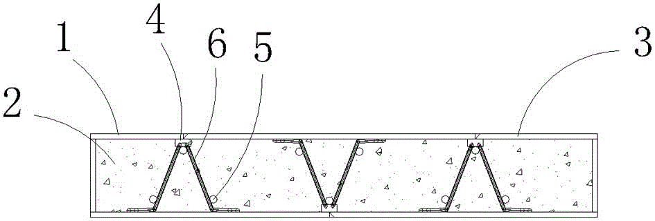
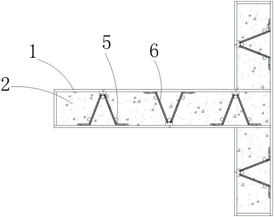
[0078] Such as figure 1 , figure 2 image 3 , Figure 4 with Figure 5 As shown, a truss-type multi-cavity steel plate shear wall includes a multi-cavity box body 1. The inner wall of the multi-cavity box body 1 is provided with at least one truss component, and the multi-cavity box body 1 is provided with Concrete 2.
[0079] The multi-cavity box body 1 is assembled by a plurality of steel plates 3, and the steel plates 3 are connected by slit welds, and the steel plates 3 on the same side are distributed in the same horizontal plane.
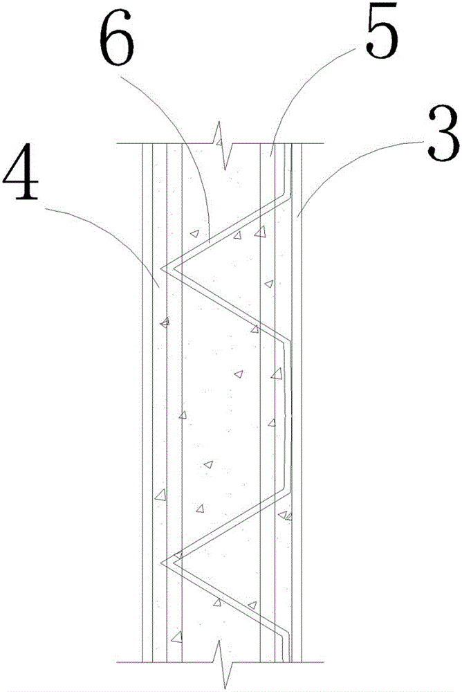
[0080] The truss assembly includes a connecting steel plate 4 and at least two longitudinal steel bars 5, and the connecting steel plate 4 and the longitudinal steel bars 5 form a triangular steel bar truss. The connecting steel plate 4 is arranged on the inner wall of the multi-cavity box 1. The two side walls of the triangular steel truss are respectively provided with connecting steel 6;
[0081] The cross section of the connecting steel bars 6 ...
Embodiment 2
[0123] Such as Image 6 , Figure 7 , Figure 8 , Picture 9 , Picture 10 with Picture 11 As shown, a truss-type multi-cavity steel plate shear wall includes a multi-cavity box body 1. The inner wall of the multi-cavity box body 1 is provided with at least one truss component, and the multi-cavity box body 1 is provided with Concrete 2.
[0124] The multi-cavity box body 1 is assembled by a plurality of steel plates 3, and the steel plates 3 are connected by slit welds, and the steel plates 3 on the same side are distributed in the same horizontal plane.
[0125] The truss assembly includes a pair of symmetrically distributed angle steels 7. The angle steels 7 are fixed to the inner wall of the multi-cavity box 1, and the angle steels 7 are provided with evenly distributed cross bars 8, and adjacent cross bars 8 are provided There are connecting plates 9 distributed obliquely with the angle steel 7;
[0126] Matching angle steel 10 is provided between adjacent truss components;
[...
Embodiment 3
[0168] Such as Picture 12 , Figure 13 , Figure 14 , Figure 15 with Figure 16 As shown, a truss-type multi-cavity steel plate shear wall includes a multi-cavity box body 1. The inner wall of the multi-cavity box body 1 is provided with at least one truss component, and the multi-cavity box body 1 is provided with Concrete 2.
[0169] The multi-cavity box body 1 is assembled by a plurality of steel plates 3, and the steel plates 3 are connected by slit welds, and the steel plates 3 on the same side are distributed in the same horizontal plane.
[0170] The truss assembly includes a connecting steel plate 4 and at least one longitudinal steel bar 5, the connecting steel plate 4 is arranged on the inner wall of the multi-cavity box 1, and the connecting steel plate 4 and the longitudinal steel bar 5 pass through connecting steel bars (6) connection.
[0171] The cross-section of the connecting steel bars 6 is continuous or spaced triangularly distributed, the longitudinal steel ba...
PUM
| Property | Measurement | Unit |
|---|---|---|
| Diameter | aaaaa | aaaaa |
| Thickness | aaaaa | aaaaa |
| Diameter | aaaaa | aaaaa |
Abstract
Description
Claims
Application Information
 - R&D
- Intellectual Property
- Life Sciences
- Materials
- Tech Scout
- Unparalleled Data Quality
- Higher Quality Content
- 60% Fewer Hallucinations
Browse by: Latest US Patents, China's latest patents, Technical Efficacy Thesaurus, Application Domain, Technology Topic, Popular Technical Reports.
© 2025 PatSnap. All rights reserved.Legal|Privacy policy|Modern Slavery Act Transparency Statement|Sitemap|About US| Contact US: help@patsnap.com