Waste water composite heat carrier generator and composite heat carrier generation method

A composite heat carrier and generator technology, applied in steam generation, steam generation device, mining fluid, etc., to achieve the effect of saving water resources, improving service life, and avoiding the effect of directly facing the combustion chamber

Active Publication Date: 2016-08-10
CNPC GLOBAL SOLUTIONS LTD +1
View PDF7 Cites 2 Cited by
  • Summary
  • Abstract
  • Description
  • Claims
  • Application Information

AI Technical Summary

Problems solved by technology

[0005] There is no prior art generator that specifically uses wastewater as a cooling water application

Method used


Image

  • Waste water composite heat carrier generator and composite heat carrier generation method
  • Waste water composite heat carrier generator and composite heat carrier generation method
  • Waste water composite heat carrier generator and composite heat carrier generation method

Examples


Embodiment approach 1

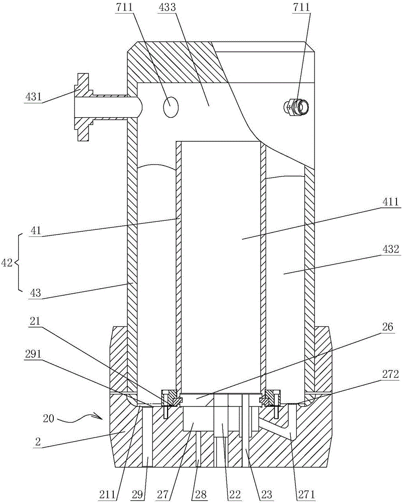
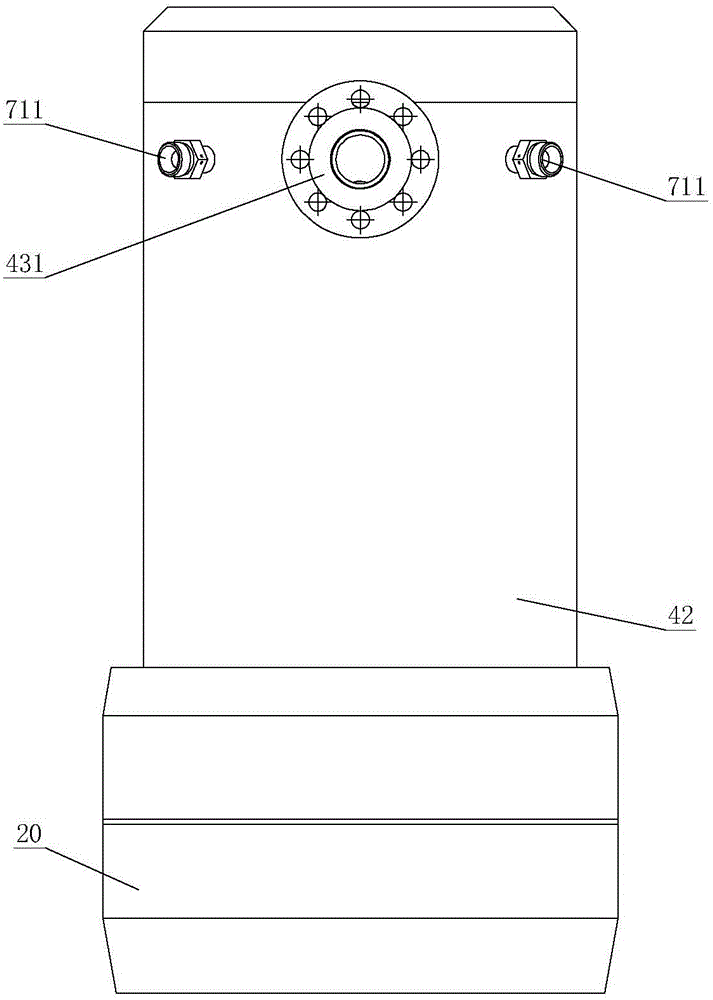
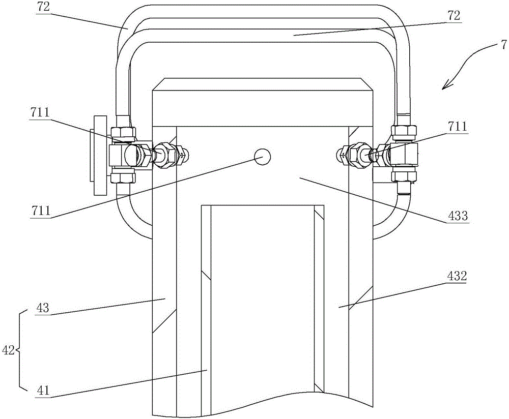
[0042] Such as Figure 1 to Figure 5As shown, the present invention provides a waste water composite heat carrier generator, which includes a generator body 42, a generator head structure 20 and a cooling gasification device 7, wherein: the generator body 42 includes a combustion chamber 41 and is sleeved in the The steam chamber 43 outside the combustion chamber 41, the upper end of the combustion chamber 41 communicates with the steam chamber 43, and the upper end of the steam chamber 43 is connected with an outlet pipe 431; the generator head structure 20 is connected to the generator The lower end of the generator body 42, the generator head structure 20 has a head body 2 and a combustion nozzle (not shown) and an ignition electrode (not shown) arranged in the head body 2, Both the combustion nozzle and the ignition electrode are arranged opposite to the combustion chamber 41, and the head body 2 is provided with a water inlet passage 28 and a scale removal passage 29 comm...

Embodiment approach 2

[0064] Such as Figure 1 to Figure 5 As shown, the present invention also provides a composite heat carrier production method of a wastewater composite heat carrier generator, the composite heat carrier production method is the composite heat carrier production method of the waste water composite heat carrier generator in Embodiment 1, and the The structure, working principle and beneficial effects of the waste water composite heat carrier generator are the same as those of Embodiment 1, and will not be repeated here. Described composite heat carrier production method comprises the steps:

[0065] a) Inject fuel into the combustion chamber 41 of the generator body 42 through the combustion nozzle, inject waste water into the steam chamber 43 of the generator body 42 through the water inlet channel 28 of the generator head structure 20, and pass through the cooling gasification device 7. Inject waste water into the steam chamber 43;

[0066] b) Open the ignition electrode, th...


PUM


Abstract

The invention provides a waste water composite heat carrier generator and a composite heat carrier generation method. The waste water composite heat carrier generator comprises a generator body, a generator head structure and a cooling gasifying device; the generator body comprises a combustion chamber and a steam chamber, the upper end of the combustion chamber is communicated with the steam chamber, and the upper end of the steam chamber is connected with an outlet pipeline; the generator head structure is connected to the lower end of the generator body, and is provided with a head body, a combustion nozzle and an ignition electrode, wherein the combustion nozzle and the ignition electrode are arranged in the head body and are arranged in a manner of being opposite to the combustion chamber, and a water inlet channel and a scale discharging channel are formed in the head body; the cooling gasifying device is connected to the upper end of the steam chamber; the generator can meet the requirements of high-pressure combustion and composite heat carrier safe output, meanwhile, waste water separated from crude oil is used as cooling water to be subject to cooling treatment through the lower portion and the upper portion of the generator, and steam needed by a composite heat carrier is generated; and clean water resources are saved, and the high cost of wastewater treatment can be reduced.

Description

technical field [0001] The invention relates to a generator and a method, in particular to a waste water composite heat carrier generator and a composite heat carrier generation method in the field of high-pressure combustion technology. Background technique [0002] Multivariate thermal fluid technology Thermal exploitation of heavy oil is a very efficient new technology, which has the advantages of high combustion efficiency, zero carbon injection, environmental protection and energy saving. Well productivity and enhanced oil recovery. [0003] The multi-component thermal fluid technology is used in oil sand mining, and its core equipment is the generator. At present, the technology of cooling and gasifying the generator with demineralized water to form a multi-component thermal fluid technology is currently a mature technology. In the process of heavy oil exploitation, the produced crude oil contains water and the wastewater after separation cannot be directly used or di...

Claims


Application Information

Patent Timeline
Patent Type & Authority Applications(China)
IPC IPC(8): F22B13/00F22B31/00E21B43/24
CPCE21B43/24F22B13/00F22B31/00F22B33/00F22B37/00
Inventor 吴耀文梅立新李国诚陈龙陆峰司军涛朱伟宋宇波梅奕中李兴儒徐梁张建忠
Owner CNPC GLOBAL SOLUTIONS LTD
Why Eureka
Try Eureka