Light filter, camera module and manufacturing method thereof

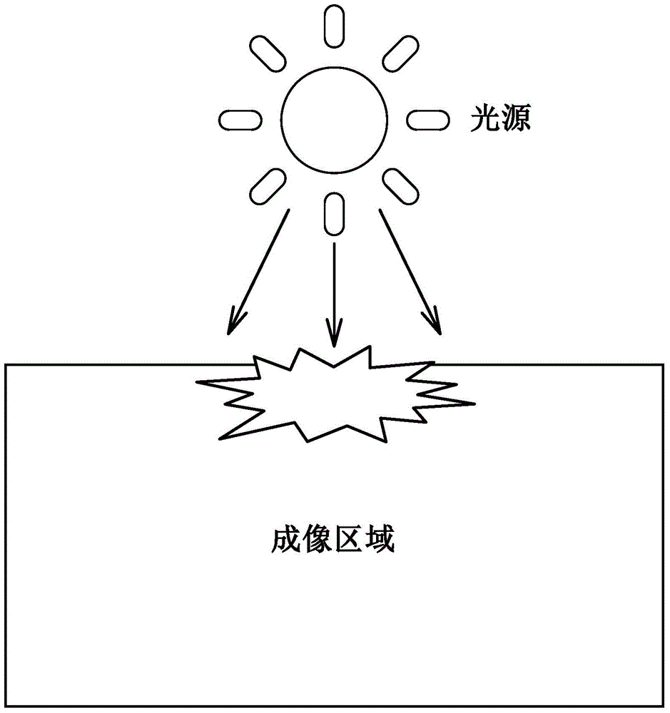
A camera module and optical filter technology, which is applied in the fields of optical filter, optics, image communication, etc., can solve the problems of stray light of camera module, affecting the image quality of mobile phone camera module, stray light, etc.

Active Publication Date: 2016-08-10
NINGBO SUNNY OPOTECH CO LTD
View PDF6 Cites 28 Cited by
  • Summary
  • Abstract
  • Description
  • Claims
  • Application Information

AI Technical Summary

Problems solved by technology

[0003] However, the existing camera modules often have the problem of stray light when shooting
figure 2 It shows that when the light source moves out of the imaging surface by 35°~40°, the edge of the corresponding position of the imaging surface presents purple-red stray light, which affects the imaging quality of the mobile phone camera module
After research and analysis, the main reason for this problem is that the large-angle light incident on the surface of the gold wire connecting the image sensor 13 and the circuit board 14 or the stray light generated by the reflection on the inner wall of the bracket 11 causes
like figure 1 As shown, the light is reflected by the raised area 111 of the window edge of the bracket 11, or reflected by the surface area 141 of several gold wires connected with the circuit board 14 and the image sensor 13, and then enters the camera module and passes through the image sensor 13 imaging, causing stray light

Method used


Image

  • Light filter, camera module and manufacturing method thereof
  • Light filter, camera module and manufacturing method thereof
  • Light filter, camera module and manufacturing method thereof

Examples


Embodiment 1

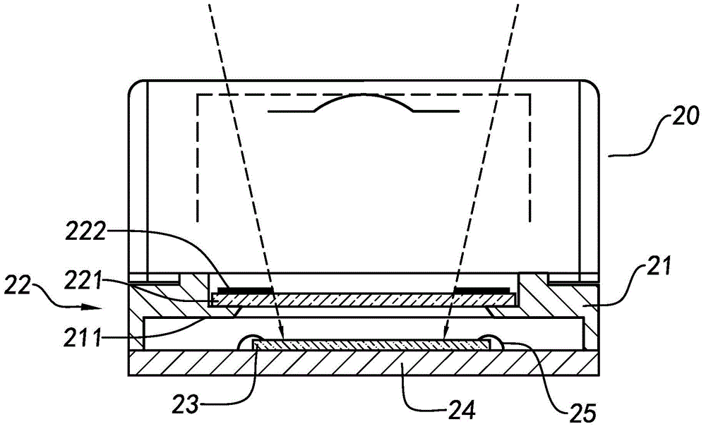
[0048] The light blocking film 222 is coated on the surface of the infrared cut filter 221 by a photolithography method, which is a traditional yellow light process.

[0049] The photoresist used in the yellow light process is a photosensitive material. The photoresist has unique characteristics. Under the action of UV light, it will undergo chemical changes and become a substance that is easily soluble in acid or alkali. Apply the photoresist on the substrate, provide the corresponding photomask according to the shape required by the product, cover the photomask on the photoresist, and then expose the photoresist so that there is no photoresist covered by the photomask A chemical change occurs in the area, and then this part of the photoresist is dissolved or retained with acid or alkali to form a pattern that is the same or complementary to the shape of the mask.

[0050] The photoresist used in the present invention is an opaque coating, which not only has the photosensitiv...

Embodiment 2

[0055] The light blocking film 222 is coated on the infrared cut filter 221 through a silk screen printing process. The ink used in the silk screen printing is an opaque material, and the ink is applied to the light blocking area of ​​the infrared cut filter 221 through a silk screen printing process, thereby forming the light blocking film 222 . The silk screen printing process can be printed by the basic principle that the mesh in the blackened position of the screen printing plate is ink-permeable, and the mesh in the light-transmitting area is impermeable to ink.

[0056] The shape of the ink-permeable part of the screen printing plate should be consistent with the shape of the light-shielding film 222, which is a ring shape. Other parts of the screen printing plate are impermeable to ink. When making, first align the screen printing plate with the infrared cut-off filter 221, pour the ink on the screen printing plate, and apply a certain amount of ink to the ink with a s...


PUM


Abstract

The invention provides a light filter capable of preventing a camera module from generating stray light, a camera module employing the light filter, and a manufacturing method of the light filter. The camera module comprises a lens, a support for fixing the lens, a light filter arranged under the lens, and an image sensor arranged under the light filter. The light filter comprises an infrared cut-off light filter and a light barrier film. The light barrier film is arranged on the infrared cut-off light filter, and the light barrier film is provided with a window in the middle so a transparent area is formed in the middle of the infrared cut-off light filter and a light barrier area is formed outside the transparent area.

Description

technical field [0001] The invention relates to the field of camera modules, in particular to an optical filter for effectively intercepting light incident on the surface of a gold wire around an image sensor and the light on an inner wall of a lens bracket and an imaging module using the filter. Background technique [0002] With the development of mobile phone camera modules in the direction of high pixel, large aperture, and ultra-thin, consumers have higher and higher requirements for the image quality of camera modules. Existing mobile phone camera modules such as figure 1 As shown, it includes a lens 10, a bracket 11 for fixing the lens 10, a filter 12 arranged under the lens 10, an image sensor 13 arranged under the filter 12, and a circuit electrically connected with the image sensor 13 plate 14. The filter 12 is mainly an infrared cut-off filter, and its function is to filter the infrared light in the light, so that the imaging effect of the camera module is close...

Claims


Application Information

Patent Timeline
Patent Type & Authority Applications(China)
IPC IPC(8): G03B17/12G02B5/20H04N5/225
Inventor 郭楠熊科强王明珠张哲宁赵波杰方银丽
Owner NINGBO SUNNY OPOTECH CO LTD
Why Eureka
Try Eureka