Camera based electronic lock system and use method
An electronic lock system and camera technology, applied in the field of electronic lock systems, can solve problems such as limited security protection, and achieve the effects of convenient comprehensive monitoring and management, strong anti-destructive performance, and high security protection
- Summary
- Abstract
- Description
- Claims
- Application Information
AI Technical Summary
Problems solved by technology
Method used
Image

Examples
Embodiment 1
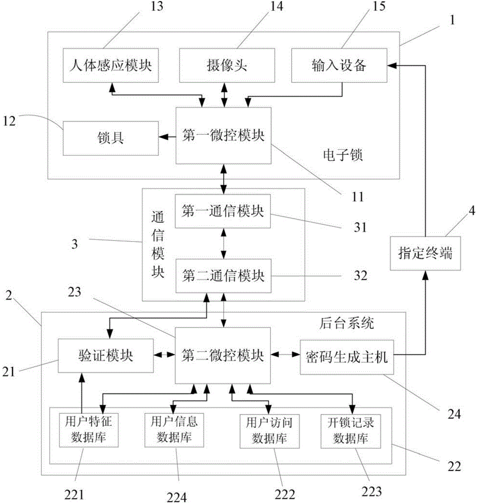
[0036] The present embodiment provides a camera-based electronic lock 1 system for bank ATMs, such as figure 1 As shown, it includes an electronic lock 1, a background system 2 and a communication module 3. The electronic lock 1 is used for the door lock of the ATM machine, and the background system 2 is a server located in the bank's background control center, and data transmission is carried out between the server and the ATM machine through the communication module 3 .
[0037] The electronic lock 1 includes a lockset 12 , a camera 14 , an input device 15 , a first micro-control module 11 and a human body sensing module 13 . The camera 14 is used to take pictures of the visitors, and the input device 15 is used for the visitors to input user verification information and transmit the user verification information to the first micro-control module 11, wherein the input device 15 in this embodiment adopts a keyboard.
[0038] The human body sensing module 13 is used to detect...
Embodiment 2
[0048] The difference from Embodiment 1 is that the communication between the first communication module 31 and the second communication module 32 is carried out through a wireless network, which can reduce the installation of lines and reduce the difficulty of wiring. Of course, the first communication module 31 and the second communication module 32 can also communicate in two ways, wired and wireless, to meet the requirements of different electronic lock systems.
Embodiment 3
[0050] The difference from Embodiment 1 is that the input device 15 is a fingerprint module, and the fingerprint module performs identification by collecting the fingerprint information of the visitor as user verification information. In addition, in this embodiment, the user password information stored in the user feature database includes at least fingerprint information, and the user information in the user information database also correspondingly includes at least user fingerprint information. According to the needs of different ATM machines and different users, different input devices 15 are selected to be set to improve the compatibility of the lockset to the electronic lock, and the fingerprint module of the present embodiment requires the user's own fingerprint to pass the verification. Input device, fingerprint verification has higher security.
[0051] In addition, the input device 15 can also be an Ibutton sensor, and the visitor can use the user-designated Ibutton...
PUM
 Abstract
Description
Claims
Application Information
 - R&D
- Intellectual Property
- Life Sciences
- Materials
- Tech Scout
- Unparalleled Data Quality
- Higher Quality Content
- 60% Fewer Hallucinations
Browse by: Latest US Patents, China's latest patents, Technical Efficacy Thesaurus, Application Domain, Technology Topic, Popular Technical Reports.
© 2025 PatSnap. All rights reserved.Legal|Privacy policy|Modern Slavery Act Transparency Statement|Sitemap|About US| Contact US: help@patsnap.com