High pressure ratio twin spool industrial gas turbine engine

A turbine engine and industrial gas technology, which is applied in the direction of gas turbine devices, engine control, engine components, etc., can solve the problems that the radius of the high rotor shaft cannot be further reduced, the performance of the turbine is not efficient, etc., and achieve the goal of improving thermodynamic efficiency and increasing inlet temperature Effect

Inactive Publication Date: 2016-08-10
FLORIDA TURBINE TECH
View PDF8 Cites 4 Cited by
  • Summary
  • Abstract
  • Description
  • Claims
  • Application Information

AI Technical Summary

Problems solved by technology

[0009] The setup of Figure 15 is the most efficient option in the current configuration for IGT engines, but is not optimal because the low rotor shaft 6 rotates within the high rotor shaft 5, and thus the high rotor shaft radius cannot be further reduced
Also, if the speed of the low rotor shaft 6 is reduced to reduce the inlet mass flow, there is a mismatch in the angle from the HPT (high pressure turbine) into the LPT (low pressure turbine), and out of the LPT (low pressure turbine) and into the PT (power turbine) mismatch of flow angles, resulting in inefficient turbine performance at part load

Method used


Image

  • High pressure ratio twin spool industrial gas turbine engine
  • High pressure ratio twin spool industrial gas turbine engine
  • High pressure ratio twin spool industrial gas turbine engine

Examples


Embodiment Construction

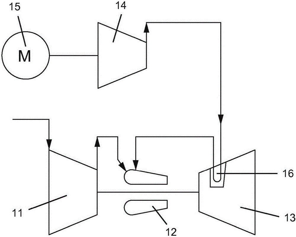
[0035] The present invention is a cooled gas turbine engine with turbine stator vanes. figure 1 A first embodiment of the invention is shown with a gas turbine engine comprising a compressor 11 , a combustion chamber 12 and a turbine 13 , wherein the compressor 11 and turbine 13 are connected together by a rotor shaft. The turbine 13 has a first stage of cooled stator vanes 16 . A compressor 11 compresses air which is then combusted with fuel in a combustor 12 to produce a flow of hot gas which is passed through a turbine 13 . The second compressor 14 is driven by a motor 15 to compress air at a higher pressure than that from the first compressor 11 . The higher compressed air then passes through stator vanes 16 in the turbine 13 for cooling, and the heated cooling gas is then passed into the combustor 12 to combine with fuel and compressed air from the first compressor 11 .

[0036] The second compressor 14 produces high pressure compressed air for cooling of the stator van...


PUM


Abstract

An industrial gas turbine engine for electrical power production includes a high pressure spool and a low pressure spool in which the low pressure spool can be operated from full power mode to zero power mode when completely shut off, where the low pressure spool is operated at high electrical demand to supply compressed air to the high pressure compressor of the high pressure spool, and where turbine exhaust is used to drive a second electric generator from steam produced in a heat recovery steam generator. The power plant can operate at 25% of peak load while keeping the unused parts of the power plant hot for easy restart when high power output is required.

Description

field of invention [0001] The present invention relates generally to industrial gas turbine engines (note: also referred to as "gas turbines"), and more particularly to dual rotor industrial gas turbine engines having a low pressure rotor that can be operated independently of a high pressure rotor. Background of the invention [0002] In a gas turbine engine, such as a large-frame heavy-duty industrial gas turbine (IGT) engine, a flow of hot gas generated in a combustor passes through a turbine to produce mechanical work. A turbine includes one or more rows or stages of stator vanes and rotor blades that react with hot gases at progressively lower temperatures. The turbine, and thus the efficiency of the engine, can be increased by passing higher temperature gases through the turbine. However, the turbine (note: aka "turbine") inlet temperature is limited by the material properties of the turbine, especially the first stage guide vanes and blades, and the amount of cooling ...

Claims


Application Information

Patent Timeline
Patent Type & Authority Applications(China)
IPC IPC(8): F01D25/16F02K3/06F02C3/107F02C7/32F02C7/36F02C1/06F02C6/00F02C3/34F02C6/08
CPCY02E20/16F01D25/162F02C1/06F02C3/107F02C3/34F02C6/003F02C6/006F02C6/08F02C7/32F02C7/36F05D2270/082
Inventor J·D·布鲁斯特梅耶J·T·赛杰卡R·B·琼斯
Owner FLORIDA TURBINE TECH
Why Eureka
Try Eureka