Cleaning system for paint particles

A coding and equipment technology, applied in the direction of using re-radiation, reflection/re-radiation of radio waves, instruments, etc., can solve problems such as reducing radar sensitivity and dynamic range

Active Publication Date: 2016-08-10
HRL LAB
View PDF10 Cites 2 Cited by
  • Summary
  • Abstract
  • Description
  • Claims
  • Application Information

AI Technical Summary

Problems solved by technology

However, previously disclosed techniques produce a non-uniformly dispersed blur, sometimes referred to as residual blur or multiplicative noise, which reduces the sensitivity and dynamic range of the radar

Method used


Image

  • Cleaning system for paint particles
  • Cleaning system for paint particles
  • Cleaning system for paint particles

Examples


Embodiment Construction

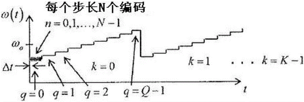
[0026] The techniques described herein apply additional measurements made within a period bounded by the distance and velocity discretization. As a result, this technique requires a faster analog-to-digital converter (ADC) than the technique used in the above-mentioned US patent application. But the advantage over the above mentioned US patent application is that the residual blur is lower than the previous application.

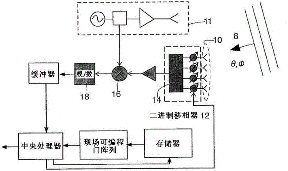
[0027] figure 1A block diagram of a CAR-encoded radar is shown, where CAR encoding is only employed in the receive part of the radar for the sake of simplicity. The possibility of using CAR also on the transmitted signal is discussed near the end of this patent. The radar is easier to design (and less complex to apply and thus less computationally expensive) if the CAR coding disclosed herein is employed only on the receiver side of the radar. As such, the receive-only embodiments disclosed herein are preferred for low-cost, short-range radar systems, such...


PUM


Abstract

A method and apparatus for reducing noise in a coded aperture radar system, the coded aperture radar system transmitting signals which occur in sweeps, with K sweeps utilized to cover field of view of the coded aperture radar system and Q frequency shifts or steps occurring each sweep thereof. An array of N antenna elements is provided, the array of antenna elements each having an associated two state modulator coupled therewith. Energy received at the array is modulated according to a sequence of multibit codes, the number of codes in the sequence of codes comprising at least K times Q times N, thereby reducing noise in the coded aperture radar system compared to a coded aperture radar system radar system having fewer than K times Q times N codes in its sequence of multibit codes.

Description

[0001] Cross References to Related Applications [0002] This application claims U.S. Provisional Patent Application Serial No. 61 / 912,990, filed December 6, 2013, entitled "Method and Apparatus for Processing Coded Aperture Radar Signals," and filed on the same date as this application, entitled "For Processing Method and Apparatus for Encoding Aperture Radar Signals," US Patent Application S / N 14 / 561,111 (Attorney Docket 629,073). The disclosures of the above-identified US Provisional Patent Application Serial No. 61 / 912,990 and US Patent Application S / N 14 / 561,111 are hereby incorporated by reference in their entireties. This application also claims priority and benefit to US Application Serial No. 14 / 561,142, filed December 4, 2014, which is hereby incorporated by reference in its entirety. [0003] This application is related to US Patent Application Serial No. 13 / 490,607, filed June 7, 2012, entitled "Coded Aperture Beam Analysis Method and Apparatus," the disclosure of w...

Claims


Application Information

Patent Timeline
Patent Type & Authority Applications(China)
IPC IPC(8): G01S7/40G01S13/34
CPCG01S13/42G01S13/58G01S2013/0236G01S7/356
Inventor 乔纳森·J·林奇
Owner HRL LAB
Why Eureka
Try Eureka