Localization-based beam forming scheme for systems with multiple antennas

A technology of beamforming and antenna, applied in the field of wireless communication system

Inactive Publication Date: 2016-08-10
MEDIATEK SINGAPORE PTE LTD SINGAPORE
View PDF7 Cites 29 Cited by
  • Summary
  • Abstract
  • Description
  • Claims
  • Application Information

AI Technical Summary

Problems solved by technology

However, in order to obtain a good Geometrical Dilution Of Precision (GDOP), the fourth ENB needs to be deployed at a relatively high position, which introduces additional costs

Method used


Image

  • Localization-based beam forming scheme for systems with multiple antennas
  • Localization-based beam forming scheme for systems with multiple antennas
  • Localization-based beam forming scheme for systems with multiple antennas

Examples


Embodiment Construction

[0024] Reference will now be made in detail to some embodiments of the invention, and examples of the invention will be described with reference to the accompanying drawings.

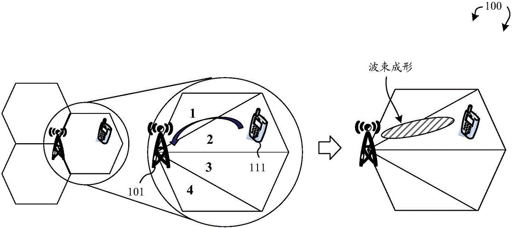
[0025] Figure 1A Is a schematic diagram of a location-based beamforming scheme in a mobile communication network 100 according to one novel aspect. The mobile communication network 100 is an LTE network, including a base station BS101 and a user equipment UE111. In the LTE-A system, a localization-based beamforming scheme can be used to enhance system performance with reduced overhead. exist Figure 1A The coverage area of ​​BS101 in the example is divided into four areas, 1, 2, 3 and 4. UE111 estimates its own location and reports its own area index (for example, area #2) to BS101. BS 101 then conducts beamforming based on the reported location information. Due to the increasing demand for Location-Based Service (LBS), location information typically comes from Global Navigation Satellite System (...


PUM


Abstract

A method of accurate 3D positioning with reduced cost is proposed. A user equipment (UE) receives a plurality of positioning reference signals (PRSs) from a plurality of base stations. The plurality of base stations includes a serving base station and two neighboring base stations. The UE estimates a plurality of line-of-sight (LOS) paths and corresponding indexes of the PRSs for time of arrival (TOA) and time difference of arrival (TDOA) measurements. The UE then estimates an elevation angle of the UE based on the estimated LOS paths of the PRS from the serving base station. Finally, the system (either UE or network, depending on where the coordinates are) can calculate the UE position based on the TDOA measurements and the elevation angle.

Description

[0001] Cross References to Related Applications [0002] This application was filed on December 26, 2013 in accordance with 35 U.S.C.§119 requirements, and the application number is 61 / 920,833 titled "A Localization-based Beamforming Scheme for Systems with Multiple Antennas" The priority of the US provisional application, the subject matter of which is hereby incorporated by reference. technical field [0003] The disclosed embodiments relate generally to wireless communication systems, and more specifically to 3-dimensional (3D) positioning using beamforming for multi-antenna systems. Background technique [0004] Wireless mobile communication systems have evolved rapidly in recent years. After the 2G and 3G systems, now the fourth generation (4th generation, 4G) wireless communication system has started to operate. In the 4G system, the Multiple-Input Multiple-Output (Multiple-Input Multiple-Output, MIMO) transmission technology has played an important role. By using ...

Claims


Application Information

Patent Timeline
Patent Type & Authority Applications(China)
IPC IPC(8): H04B7/06
CPCH04W16/28G01S5/10G01S5/12G01S1/14G01S5/0036H04W64/006H04W88/02H04B7/0617G01S5/0027H04L5/0023
Inventor 吴文榕王运凯
Owner MEDIATEK SINGAPORE PTE LTD SINGAPORE
Why Eureka
Try Eureka