
Polishing device for robot-terminal flexible motorized spindle

A polishing device and flexible electric technology, applied in surface polishing machine tools, grinding/polishing equipment, grinding workpiece supports, etc., can solve the problem of inability to adapt to small tolerance changes on the surface of workpieces, difficulty in achieving high-precision surface quality, and changing Long process cycle and other issues can be achieved to improve the efficiency of grinding and polishing, reduce the cost of consumables, and ensure high quality

Active Publication Date: 2016-08-17
NORTHWESTERN POLYTECHNICAL UNIV +1
View PDF8 Cites 8 Cited by
  • Summary
  • Abstract
  • Description
  • Claims
  • Application Information

AI Technical Summary

Problems solved by technology

[0002] At present, most of the small electric spindles used in precision machining are used in machine tool equipment to deal with the chamfer after machining, deburring and surface polishing. The machine tool itself has strong rigidity, high position accuracy, and good consistency of machining trajectory, but it cannot adapt to the workpiece. Small tolerance changes on the surface, it is difficult to achieve high precision of surface quality
Moreover, due to the limitation of the machine tool structure, compared with robots, its application scalability is poor, and the change process cycle is long.
[0003] At present, there is no small-scale electric spindle processing device specially used for robots. Applying small electric spindles to robots can give full play to the advantages of flexible production of process robots. It is convenient to change processes, good accessibility, and good scalability.

Method used


Image

  • Polishing device for robot-terminal flexible motorized spindle
  • Polishing device for robot-terminal flexible motorized spindle
  • Polishing device for robot-terminal flexible motorized spindle

Examples


Embodiment Construction

[0031] The present invention will be described in detail below in conjunction with specific embodiments. The following examples will help those skilled in the art to further understand the present invention, but do not limit the present invention in any form. It should be noted that those skilled in the art can make several changes and improvements without departing from the concept of the present invention. These all belong to the protection scope of the present invention.

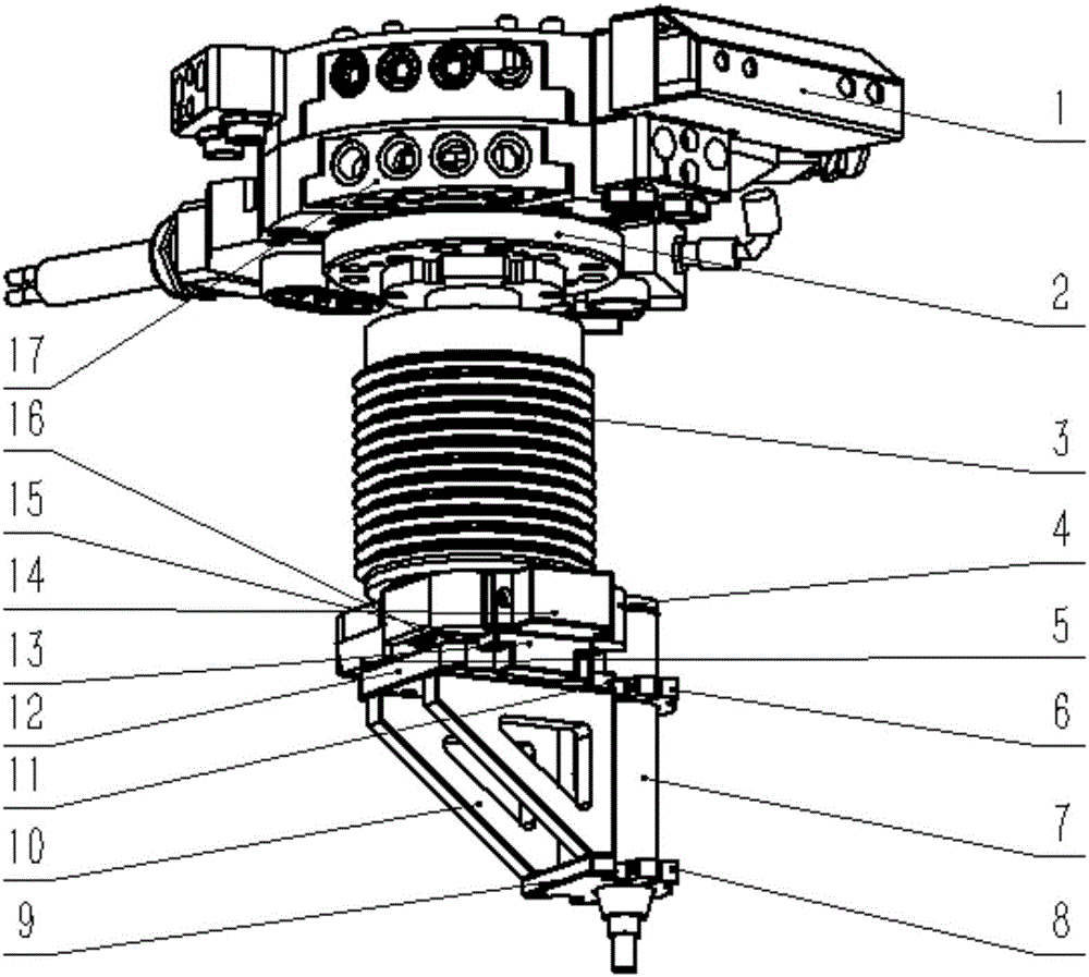
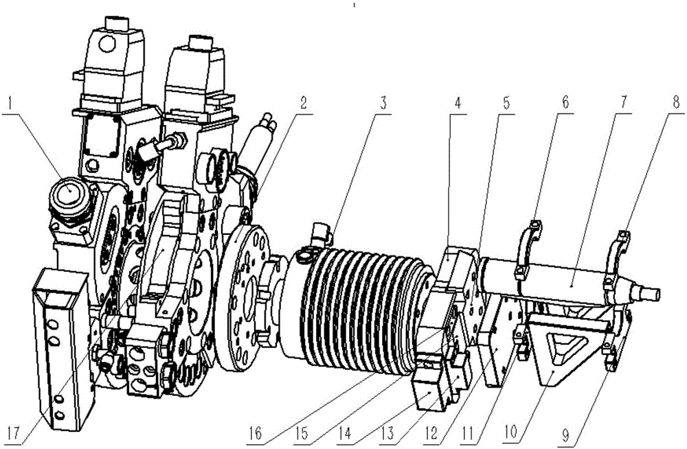
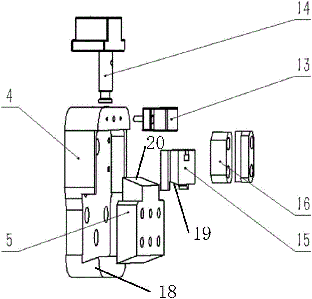
[0032] Such as figure 1 , figure 2 As shown, the robot end-type flexible electric spindle polishing device provided by the present invention includes a quick-change male disc 1 connected to the end of the robot (such as the sixth axis), an end flange 2 connected to a flexible flange 3, a flexible flange 3. Inner concave block of the locking mechanism 4, guide connecting block 5, semicircle snap ring at the upper end of the electric spindle 6, electric spindle 7, semicircle snap ring at the lower end o...


PUM


Abstract

The invention provides a polishing device for a robot-terminal flexible motorized spindle, comprising a quick-change male disc, a quick-change female disc, a terminal flange, a flexible flange, an auto-locking mechanism, a motorized spindle clamping device and a motorized spindle that are connected in succession; the quick-change male disc and the quick-change female disc are detachably connected; the motorized spindle clamping device is detachably connected with the auto-locking mechanism. By introducing the flexible flange, it is possible to control and adjust in real time, nominal force for the motorized spindle during polishing; automatic polishing by robot replacing labor is achieved, and the problem that a severe field environment for polishing causes health damage to workers is solved; the polishing device has constant polishing force, the matching problem between a robot fixed processing path and a workpiece tolerance is solved, stable polishing process parameters are maintained, high bearing capacity and stability of a robot are made full use, polishing efficiency is improved greatly, consumables cost is reduced, the service life of tooling is prolonged, and homogenous high-level polishing quality is guaranteed.

Description

technical field [0001] The invention relates to a flexible grinding electric spindle, in particular to a polishing device for a robot-end type flexible electric spindle. Background technique [0002] At present, most of the small electric spindles used in precision machining are used in machine tool equipment to deal with the chamfer after machining, deburring and surface polishing. The machine tool itself has strong rigidity, high position accuracy, and good consistency of machining trajectory, but it cannot adapt to the workpiece. Small tolerance changes on the surface make it difficult to achieve high precision in surface quality. Moreover, limited by the machine tool structure, compared with robots, its application scalability is poor, and the process change cycle is long. [0003] At present, there is no small electric spindle processing device specially used for robots. Applying small electric spindles to robots can give full play to the advantages of flexible product...

Claims


Application Information

Patent Timeline
Patent Type & Authority Applications(China)
IPC IPC(8): B24B29/02B24B41/06
CPCB24B29/02B24B41/06
Inventor 李山黄新春王道清胡建勇胡小龙杨伟谢少波
Owner NORTHWESTERN POLYTECHNICAL UNIV
Learn More