Plastic pipe punching device

A punching device and plastic pipe technology, applied in metal processing, etc., can solve problems such as low processing efficiency and cumbersome operation, and achieve the effects of high pass rate, precise punching position, and reduced processing cost

Active Publication Date: 2016-08-17
永嘉县安邦塑钢工程有限公司
View PDF8 Cites 8 Cited by
  • Summary
  • Abstract
  • Description
  • Claims
  • Application Information

AI Technical Summary

Problems solved by technology

The traditional plastic pipe punching device can only punch holes in one direction on the plastic pipe at a time, and when the plastic pipe is required to be punched in multiple directions, the operation is cumbersome and the processing efficiency is low. Therefore, it is urgent to develop a structure Simple, easy to use, can punch holes in multiple directions at the same time, and a plastic pipe punching device with high processing efficiency

Method used


Image

  • Plastic pipe punching device
  • Plastic pipe punching device
  • Plastic pipe punching device

Examples


Embodiment Construction

[0038] The following will clearly and completely describe the technical solutions in the embodiments of the present invention with reference to the accompanying drawings in the embodiments of the present invention. Obviously, the described embodiments are only some, not all, embodiments of the present invention. Based on the embodiments of the present invention, all other embodiments obtained by persons of ordinary skill in the art without making creative efforts belong to the protection scope of the present invention.

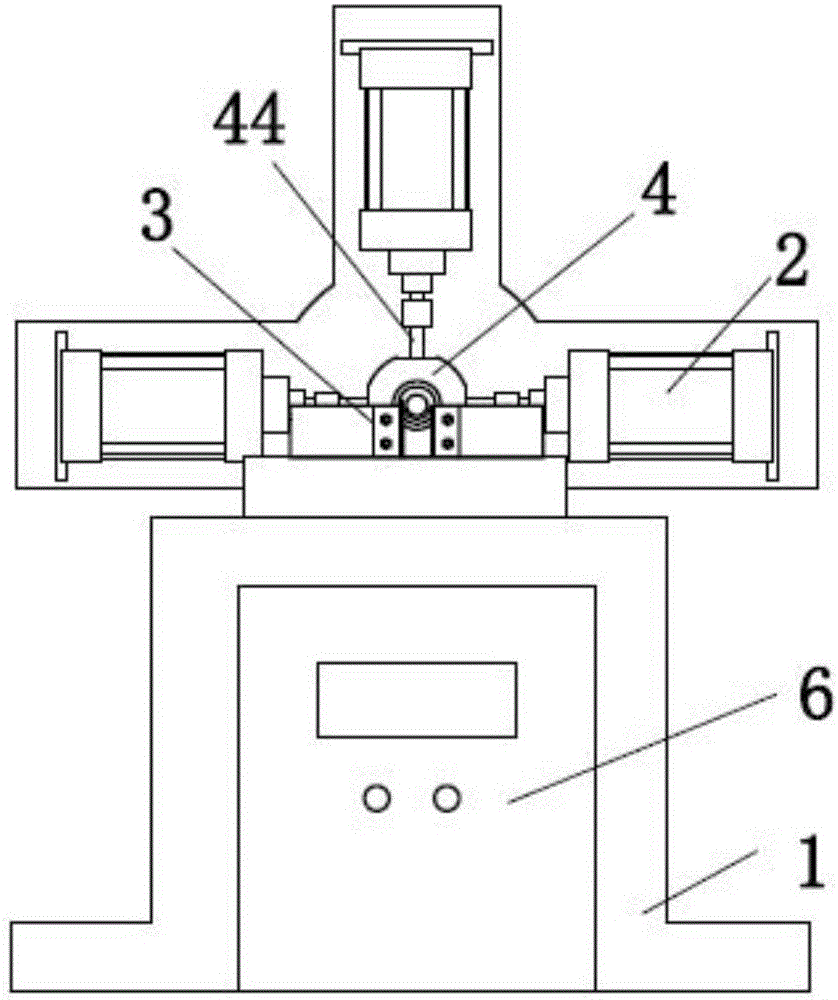
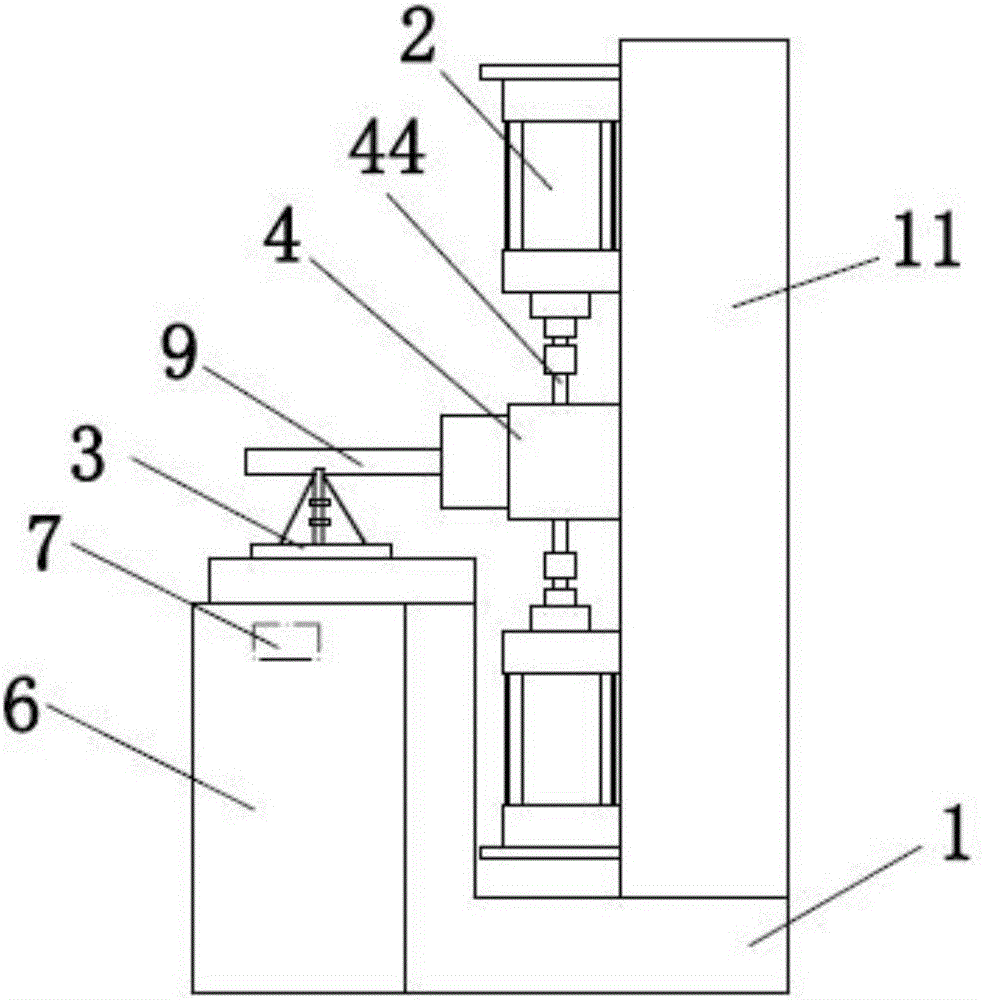
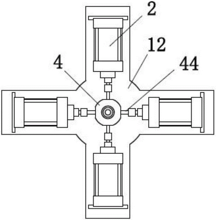
[0039] refer to Figure 1 to Figure 13 ,like figure 1 with figure 2 A plastic pipe punching device shown includes: a base 1 , a driving device, a mold 4 , a clamping device 8 and a control device 6 , and the driving device is fixedly arranged on the base 1 .

[0040] The mold 4 is fixedly arranged on the base 1, such as Figure 5 As shown, the mold 4 includes a guide mold 41 and a core mold 42, the core mold 42 is sleeved in the guide mold 41, and parts ar...


PUM


Abstract

The invention discloses a plastic pipe punching device. The plastic pipe punching device comprises a base, a driving device, a mould, a clamping device and a control device. The mould is fixedly arranged on the base and comprises a guide mould body, a core mould body and a punch, wherein the guide mould body sleeves the core mould body, a part holding cavity is formed between the inner wall of the guide mould body and the periphery of the core mould body, and the punch is connected to the driving device. The driving device drives the punch to pass through a guide hole of the guide mould body and a punching hole of the core mould body to punch a plastic pipe. The clamping device is arranged in an end cover of the mould and used for clamping the plastic pipe. The plastic pipe punching device is simple in structure and convenient to use and is high in machining efficiency by achieving multi-directional punching simultaneously.

Description

technical field [0001] The invention relates to the technical field of plastic pipe processing equipment, in particular to a plastic pipe punching device. Background technique [0002] Plastic pipes have the characteristics of light weight, corrosion resistance, high compressive strength, long service life, and convenient installation, and are favored by the pipeline engineering industry. Due to the needs of on-site installation, holes are often processed on the pipe wall of the plastic pipe to facilitate the installation of other workpieces. The traditional plastic pipe punching device can only punch holes in one direction on the plastic pipe at a time, and when the plastic pipe is required to be punched in multiple directions, the operation is cumbersome and the processing efficiency is low. Therefore, it is urgent to develop a structure Simple, easy to use, can punch holes in multiple directions at the same time, and is a plastic pipe punching device with high processing...

Claims


Application Information

Patent Timeline
Patent Type & Authority Applications(China)
IPC IPC(8): B26F1/02B26D7/02
CPCB26D7/02B26D2007/013B26F1/0015B26F1/02
Inventor 林庆
Owner 永嘉县安邦塑钢工程有限公司
Why Eureka
Try Eureka