
Laser engraving machine

A laser engraving machine and laser engraving technology, applied in typewriters, printing, etc., can solve problems such as easy to be stained, scratched, less responsive to two-dimensional codes, poor printing effect, etc., to avoid damage and improve operating speed Fast and shorten the effect of engraving time

Inactive Publication Date: 2016-08-17
SUZHOU ENOUXI INTELLIGENT TECH CO LTD
View PDF11 Cites 2 Cited by
  • Summary
  • Abstract
  • Description
  • Claims
  • Application Information

AI Technical Summary

Problems solved by technology

At present, most of them use inkjet coding technology, manual ribbon coding technology, electric engraving technology and sticker quality labels, etc., which consume more materials and high cost; traditional methods mostly use manual or semi-automatic printing, which consumes a lot of labor, and The printing effect is not good, and it is easy to be stained and scratched off, making it impossible to distinguish. Also, some printed products will fall off and information will be missing. It is less able to correspond to QR codes and foreign characters

Method used


Image

  • Laser engraving machine
  • Laser engraving machine
  • Laser engraving machine

Examples


Embodiment Construction

[0022] The specific implementation manners of the present invention will be further described in detail below in conjunction with the accompanying drawings and embodiments. The following examples are used to illustrate the present invention, but are not intended to limit the scope of the present invention.

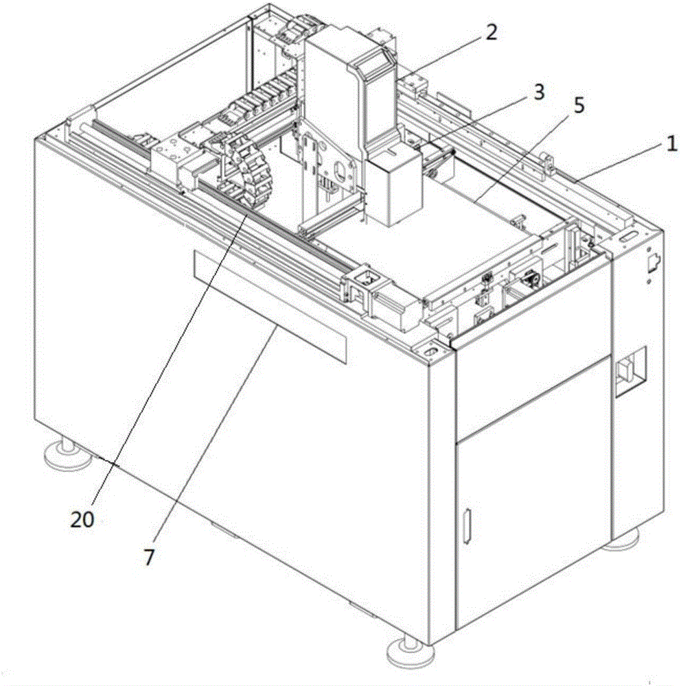
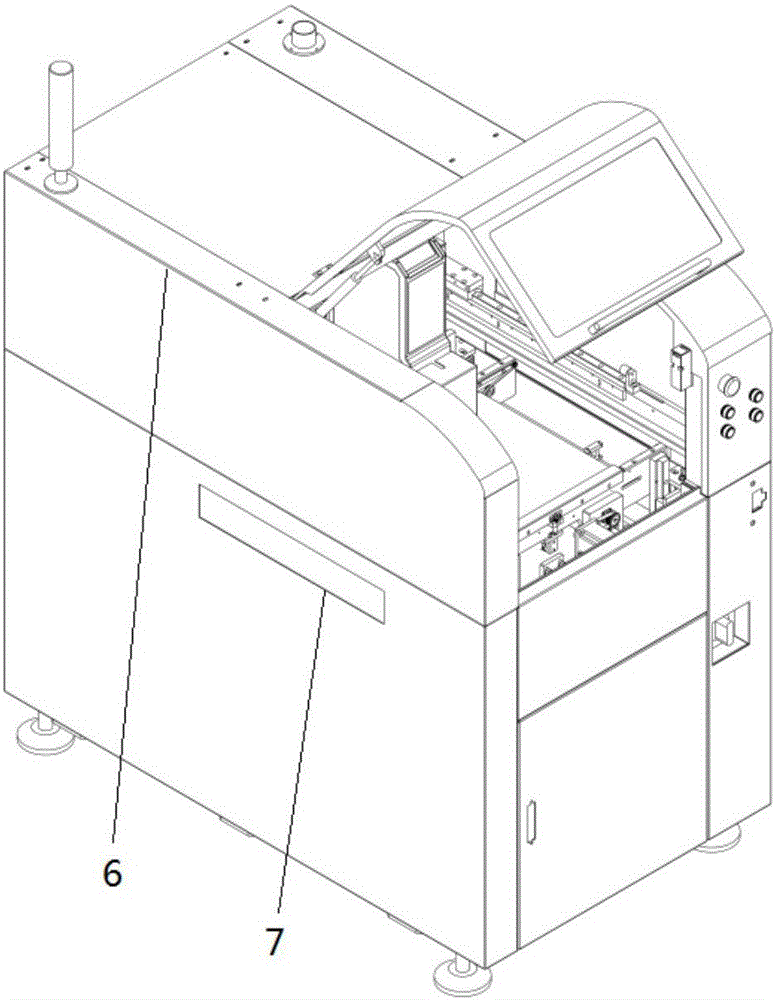
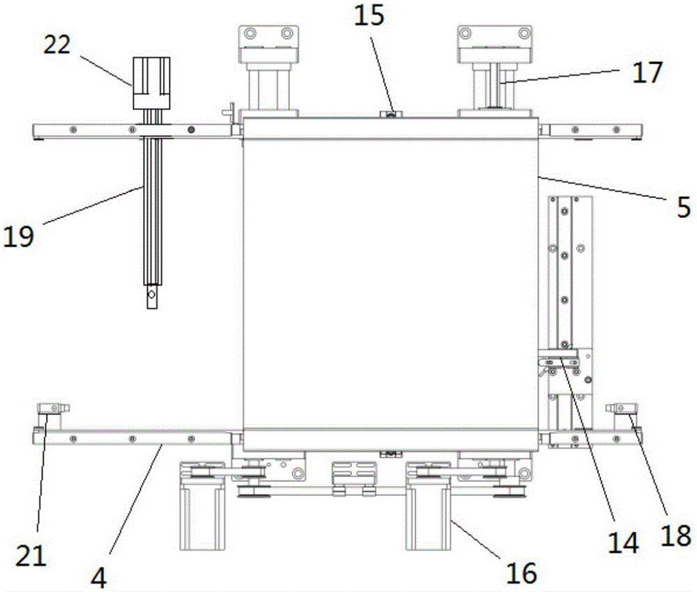
[0023] see Figure 1 to Figure 4 A laser engraving machine described in a preferred embodiment of the present invention includes a frame 1, a laser engraving unit arranged on it and a feeding unit facing the laser engraving unit, and the laser engraving unit includes a The laser 2 and the scanning camera 3 that the frame 1 moves horizontally; the feeding unit includes a feeding belt facing the laser 2 and the scanning camera 3, the feeding belt includes two The belt 4 driven by the first transmission mechanism of the belt 4 is provided with a stop device capable of blocking the product 5 to be laser engraved on the belt 4 between the two belts 4; the frame 1 is covered wi...


PUM


Abstract

The invention aims to provide a laser engraving machine which is high in code printing efficiency, good in quality and wide in application range. The laser engraving machine comprises a machine frame, a laser engraving unit and a feeding unit, wherein the laser engraving unit is arranged on the machine frame, and the feeding unit right faces the laser engraving unit. The laser engraving unit comprises a laser device and a scanning camera which horizontally move along the machine frame. The feeding unit comprises a feeding belt which right faces the laser device and the scanning camera. The feeding belt is driven by a transmission mechanism on the machine frame. According to the laser engraving machine, using of wastage materials is avoided, and the using cost is greatly reduced; and the code printing quality is high, and compared with label printing or pasting, the phenomena of defacing, scraping, disengagement and the like are avoided.

Description

technical field [0001] The invention relates to an automatic equipment, in particular to a laser engraving machine. Background technique [0002] With the continuous development of electronic technology, various materials emerge in an endless stream, and the information that needs to be printed and engraved on the product is becoming more and more complex and diverse. At present, most of them use inkjet coding technology, manual ribbon coding technology, electric engraving technology and sticker quality labels, etc., which consume more materials and high cost; traditional methods mostly use manual or semi-automatic printing, which consumes a lot of labor, and The printing effect is not good, it is easy to be stained and scratched off, making it impossible to distinguish, and some printed products will fall off and information will be missing, etc.; For QR codes and foreign characters, it is less able to correspond. [0003] In view of the above-mentioned defects, the desig...

Claims


Application Information

Patent Timeline
Patent Type & Authority Applications(China)
IPC IPC(8): B41J2/435B41J3/44B41J3/407B41J3/413B41J3/01
CPCB41J2/435B41J3/01B41J3/4075B41J3/413B41J3/44
Inventor 高磊郭飞
Owner SUZHOU ENOUXI INTELLIGENT TECH CO LTD
Learn More