Composite waterborne floating-body rack system for photovoltaic power generation and manufacturing process of composite waterborne floating-body rack system for photovoltaic power generation

A composite material and photovoltaic power generation technology, applied in the field of floating platforms, can solve problems such as the difficulty in meeting the 25-year life cycle requirements of photovoltaic power plants, and achieve the effect of improving the service life

Inactive Publication Date: 2016-08-17
NANJING UNIV OF TECH
View PDF6 Cites 15 Cited by
  • Summary
  • Abstract
  • Description
  • Claims
  • Application Information

AI Technical Summary

Problems solved by technology

The floating unit in the existing floating body platform is usually made of high-density polyethylene material, and its service life is about 15 years, which is difficult to meet the requirements of the 25-year life cycle of photovoltaic power plants

Method used


Image

  • Composite waterborne floating-body rack system for photovoltaic power generation and manufacturing process of composite waterborne floating-body rack system for photovoltaic power generation
  • Composite waterborne floating-body rack system for photovoltaic power generation and manufacturing process of composite waterborne floating-body rack system for photovoltaic power generation
  • Composite waterborne floating-body rack system for photovoltaic power generation and manufacturing process of composite waterborne floating-body rack system for photovoltaic power generation

Examples


Embodiment Construction

[0037] The present invention will be further described below in conjunction with the accompanying drawings and specific embodiments.

[0038] Such as Figure 1-17 Shown:

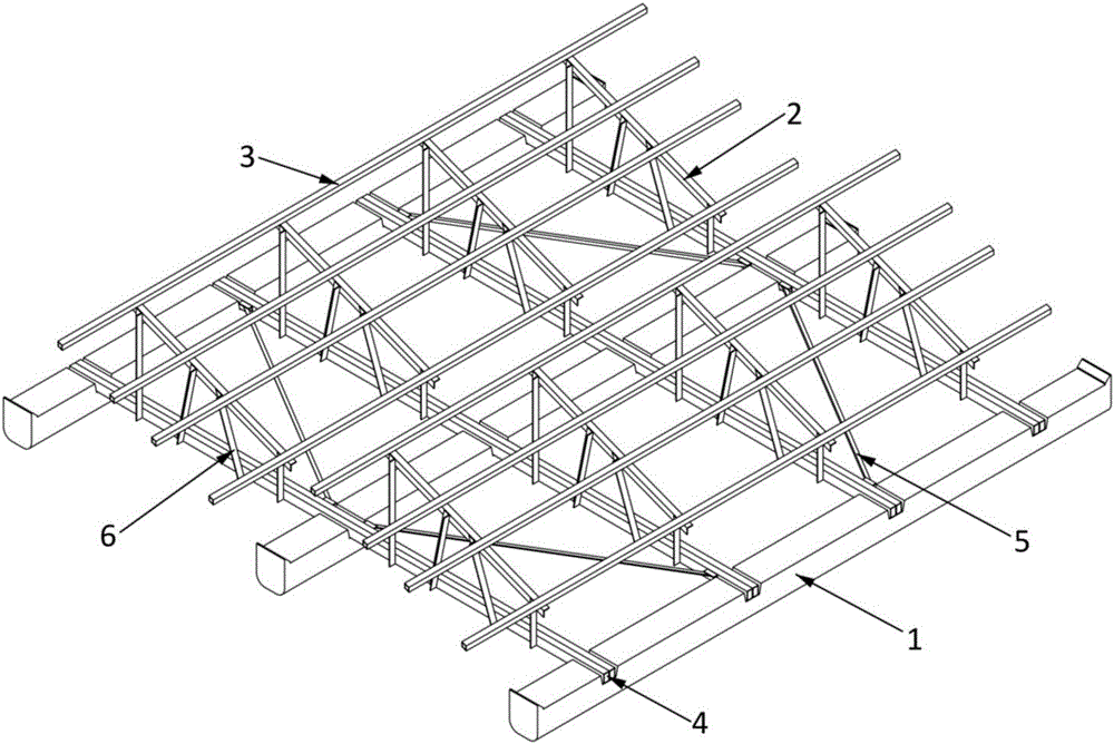
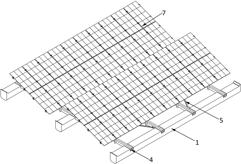
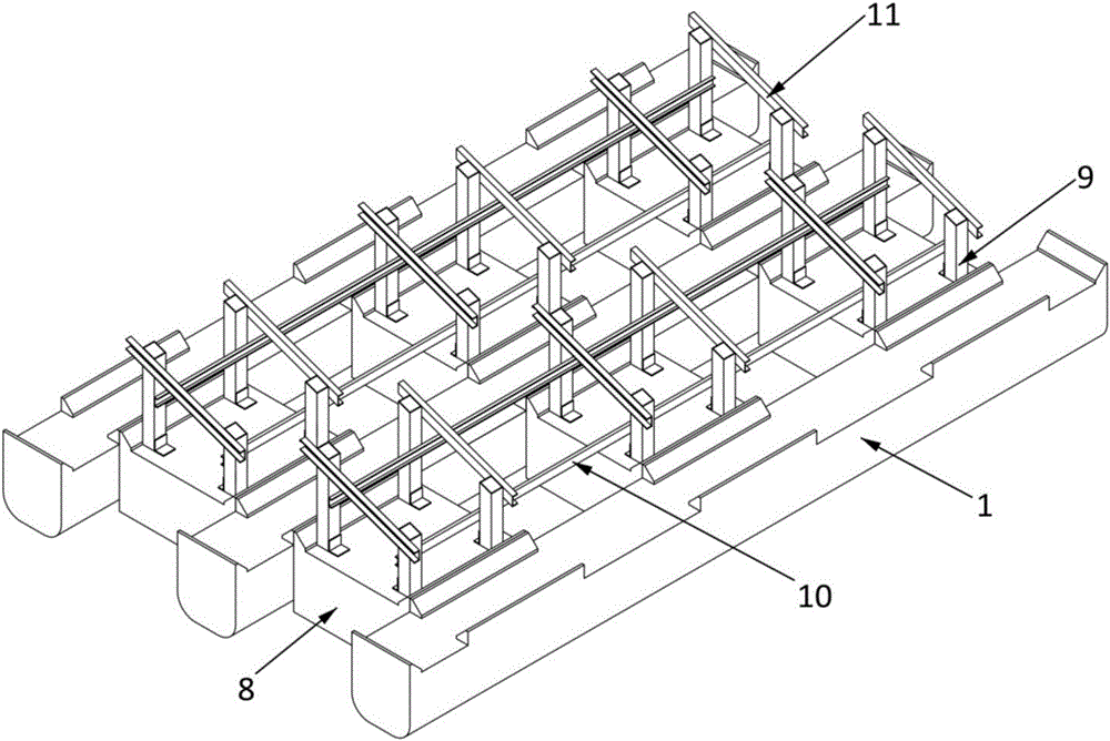
[0039] A composite material water floating body platform system for photovoltaic power generation, the floating body platform system includes a composite material floating body unit A1, a composite material glued beam 4 or a composite material floating body unit B8, and a composite material pultrusion profile;

[0040]When the composite material glued beam 4 is used: the upper surface of the composite material floating body unit A1 is provided with grooves at intervals, and the composite material glued beam 4 is placed in the groove, and is connected to the composite material floating body unit A1 through bolts 12 Connecting multiple composite floating body units A1 horizontally into a whole; the composite floating body unit A1 is provided with embedded steel sheets 13, and the embedded steel sheets 13 are ...


PUM

PropertyMeasurementUnit
lengthaaaaaaaaaa
lengthaaaaaaaaaa

Abstract

The invention discloses a composite waterborne floating-body rack system for photovoltaic power generation and a manufacturing process of the composite waterborne floating-body rack system for photovoltaic power generation. The composite waterborne floating-body rack system comprises a plurality of composite floating-body units A, composite bonding beams or composite floating-body units B and composite pultruded sections. When the composite bonding beams are adopted, the upper surface of each of the composite floating-body units A is provided with grooves at intervals, the composite bonding beams are disposed in the grooves and are connected with the composite floating-body units A through bolts, and the composite floating-body units A are connected transversely to form a whole; when the composite floating-body units B are adopted, the composite floating-body units A and the composite floating-body units B are connected into a whole through embedded steel sheets. The composite waterborne floating-body rack system for photovoltaic power generation is applicable to construction of waterborne photovoltaic power stations and substitutes the composite floating-body units and the pultruded sections for high-density polyethylene floating-body units and galvanized steel supports respectively, so that service life of the whole composite waterborne floating-body rack system is prolonged.

Description

technical field [0001] The invention relates to the technical field of floating platforms, in particular to a composite material floating platform system for photovoltaic power generation on water, which is green and environmentally friendly, has a long life cycle and low maintenance costs, and a production process thereof. Background technique [0002] With the development of my country's economy and society, my country's photovoltaic power generation has entered a stage of rapid development. According to statistics, by the end of 2015, my country's cumulative installed capacity of photovoltaic power generation reached 43 million kilowatts, surpassing Germany to become the world's largest photovoltaic market. One of the disadvantages of photovoltaic power plants is that energy is scattered and occupies a large area. Therefore, my country strictly restricts the use of cultivated land for photovoltaic power plants and encourages photovoltaics to use Gobi, desert, and barren mo...

Claims


Application Information

Patent Timeline
Patent Type & Authority Applications(China)
IPC IPC(8): B63B35/44B63B9/06H02S20/00
CPCB63B35/44B63B75/00B63B2035/4453B63B2231/52H02S20/00Y02E10/50
Inventor 刘伟庆方海李晓龙齐玉军彭小婕王璐王俊方园
Owner NANJING UNIV OF TECH
Why Eureka
Try Eureka