A liquid storage pot, liquid storage tank butt joint discharge control system and method
A control method and technology for a liquid storage tank, which are used in liquid distribution, conveying or transfer devices, special distribution devices, packaging, etc., can solve the problems of oil or special liquids being difficult to supervise and unloading at will, and improve the safety performance of unloading. , the effect of ensuring safety and strengthening supervision
- Summary
- Abstract
- Description
- Claims
- Application Information
AI Technical Summary
Problems solved by technology
Method used
Image

Examples
Embodiment 1
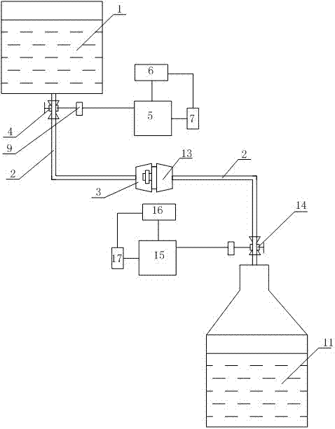
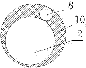
[0039] Such as Figures 1 to 2As shown, a liquid storage pot and liquid storage tank docking liquid discharge control system and method of the present invention include a liquid storage tank body 1, and the liquid storage tank body 1 can use an existing box body. The feature of the present invention is that the liquid storage There is an oil outlet at the bottom of the tank body 1, and a non-detachable fuel tank electronic valve 4 is installed on the oil outlet. Once the fuel tank electronic valve 4 is removed, an irreversible gap will be formed, and then the oil delivery pipe 2 is connected to the fuel tank electronic valve. On the valve 4, and adopt detachable structure to connect at the same time, the end of the fuel delivery pipe 2 is connected with a fuel tank nozzle 3, as a simple replacement, the fuel tank electronic valve 4 can also be set on the fuel delivery pipe 2, the fuel tank electronic valve 4, the fuel delivery pipe 2, And the oil outlets are connected by non-d...
Embodiment 2
[0045] Such as Figures 1 to 2 As shown, the difference between this embodiment and Embodiment 1 is only the difference in the control method:
[0046] (a) Communicatively connect the fuel tank microcontroller 5 on the liquid storage tank body 1 with the oiler controller 15 on the oiler body 11;
[0047] (b) The signal control terminal sends an instruction to the oiler controller 15, and the oiler controller 15 reads the information of the liquid storage tank body 1 stored on the microcontroller 5 of the oil tank after receiving the instruction;
[0048] (c) The oiler controller 15 performs calculation and judgment on the read information of the liquid storage tank body 1, and if the read information of the liquid storage tank body 1 is correct, it sends an instruction to trigger the fuel tank electronic valve 4 through the fuel tank microcontroller 5 Start to drain the oil, and trigger the electronic valve 14 of the oil pot to start receiving; if the read information of the ...
Embodiment 3
[0051] Such as Figures 1 to 2 As shown, the difference between this embodiment and Embodiment 1 is only the difference in the control method:
[0052] (a) Communicatively connect the fuel tank microcontroller 5 on the liquid storage tank body 1 with the oiler controller 15 on the oiler body 11;
[0053] (b) The signal control terminal sends instructions to the fuel tank micro-controller 5 and the oil pot controller 15 respectively. After receiving the commands, the fuel tank micro-controller 5 reads the information of the oil pot body 11 stored on the oil pot controller 15, and the oil pot After the controller 15 receives the instruction, it reads the information of the liquid storage tank body 1 stored on the fuel tank microcontroller 5;
[0054] (c) Calculation and judgment: If the information of the oil tank body 11 read by the fuel tank microcontroller 5 is correct, and at the same time the information of the liquid storage tank body 1 read by the oil tank controller 15 ...
PUM
 Abstract
Description
Claims
Application Information
 - R&D
- Intellectual Property
- Life Sciences
- Materials
- Tech Scout
- Unparalleled Data Quality
- Higher Quality Content
- 60% Fewer Hallucinations
Browse by: Latest US Patents, China's latest patents, Technical Efficacy Thesaurus, Application Domain, Technology Topic, Popular Technical Reports.
© 2025 PatSnap. All rights reserved.Legal|Privacy policy|Modern Slavery Act Transparency Statement|Sitemap|About US| Contact US: help@patsnap.com