Gravity type self-anchorage connecting device and assembly method

A connecting device, gravity-type technology, applied in the direction of construction, building construction, etc., can solve the problems that cannot be used to connect building prefabricated parts, inconvenient to open, etc., to achieve the effect of ensuring durability, meeting long-term use, and reducing pollution

Active Publication Date: 2016-08-17
SHANDONG TONGYUAN DESIGN GRP
View PDF5 Cites 4 Cited by
  • Summary
  • Abstract
  • Description
  • Claims
  • Application Information

AI Technical Summary

Problems solved by technology

[0005] However, in the existing expansion bolts, a torsion force must be applied to the nut so that the bolt head can move outward.
However, based on the needs of the overall connection strength of building components, it is not convenient to open through holes for fastening nuts
Therefore, the existing expansion bolts can hardly be used to connect two building prefabricated parts

Method used


Image

  • Gravity type self-anchorage connecting device and assembly method
  • Gravity type self-anchorage connecting device and assembly method
  • Gravity type self-anchorage connecting device and assembly method

Examples


Embodiment 1

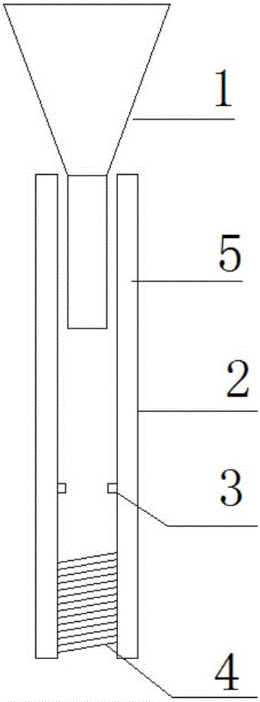
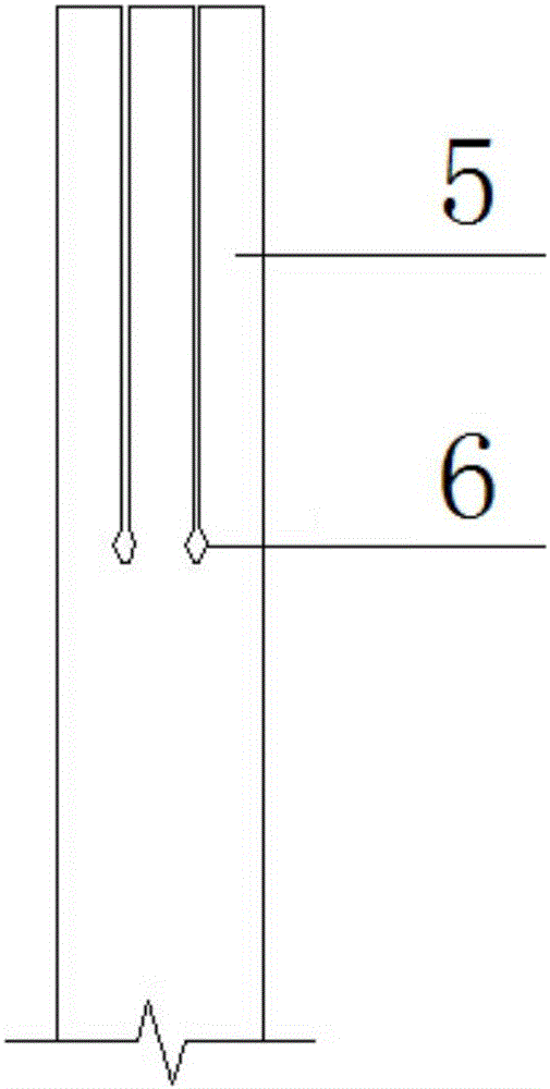
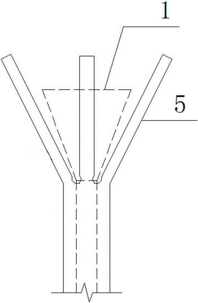
[0032] Embodiment 1: a kind of gravity type self-anchored connecting device, its structure is as follows Figure 1-3 Shown: includes a sleeve 2 with openings at both ends. The lower end of the sleeve 2 has a sleeve thread 4 for connecting the external steel bars of the building components. The upper end of the sleeve 2 is an expansion part 5, and an expansion part is inserted into the expansion part 5 head 1.

[0033] The expansion head 1 includes an integrally formed rod and a head, and the diameter of the largest part of the head is larger than the outer diameter of the sleeve 2 . And the head is in the shape of a truncated cone.

[0034] In order to facilitate expansion of the expansion part 5 , in this embodiment, a weakened part 6 is provided on the expansion part 5 .

[0035] From the perspective of accurate and convenient construction, a limiting protrusion 3 is provided inside the sleeve 2 , and the limiting protrusion 3 is located between the weakened portion 6 and ...

Embodiment 2

[0036] Embodiment 2: as Figure 4 As shown, a method for assembling two building components using the gravity-type self-anchoring connection device described in Embodiment 1, its main steps are as follows:

[0037] A, threading on the extended reinforcing bar of the first building component 7, so that the extending reinforcing bar 9 of the first building component 7 and the sleeve thread 4 at the lower end of the sleeve 2 form a thread pair;

[0038] B. Rotate the sleeve 2 until the outstretched steel bar is tight against the limit protrusion 3;

[0039] C, the expansion head 1 is placed in the reserved hole 10 of the second building component 8;

[0040] D. Loosen the second building component, so that the second building component 8 moves relative to the first building component by gravity, and the expansion head 1 is pressed down to move, so that the expansion part 5 expands and expands at the weakened part 6, and the expanded part The expansion part 5 forms a self-anchor...


PUM


Abstract

The invention relates to a gravity type self-anchorage connecting device and an assembly method and belongs to the field of relevant technical equipment of constructional engineering. The gravity type self-anchorage connecting device mainly comprises a sleeve, and the two ends of the sleeve are open. The lower end of the sleeve is provided with a sleeve thread used for being connected with a protruding bar of a building component. The upper end of the sleeve serves as an expansion part. An expansion head is inserted in the upper end of the sleeve. The expansion head comprises a rod part and a head part which are formed integrally. The diameter of the largest portion of the head part is larger than the outer diameter of the sleeve. According to the gravity type self-anchorage connecting device and the assembly method, two prefabricated building components can be connected rapidly and conveniently through the design of a brand-new connecting component structure.

Description

technical field [0001] The invention relates to the technical equipment field related to construction engineering, in particular to a gravity self-anchoring connection device and an assembly method. Background technique [0002] At present, as my country's construction industry enters a new development process, especially the development of reinforcement technology and prefabricated structure technology, building concrete components often need to be connected. [0003] In the past connection technology, the connection structure is complex and the operation is cumbersome, such as bolts need to be screwed on site. Limited by the overall cost, and the screwing tools are only ordinary wrenches rather than torque wrenches, the technical level of construction workers determines the quality of bolt installation. Post-planting reinforcement technology requires on-site glue injection, the durability of the glue cannot be guaranteed, and it cannot meet the requirements of long-term u...

Claims


Application Information

Patent Timeline
Patent Type & Authority Applications(China)
IPC IPC(8): E04B1/38
CPCE04B1/38
Inventor 齐政魏强李俊峰
Owner SHANDONG TONGYUAN DESIGN GRP
Why Eureka
Try Eureka