Structure of roof tile unit

A unit body and tile technology, applied in the field of roof tiles, can solve the problem of rainwater infiltrating the top of buildings, etc.

Inactive Publication Date: 2016-08-17
HUBEI XINXINLAN ENVIRONMENTAL PROTECTION TECH CO LTD
View PDF7 Cites 2 Cited by
  • Summary
  • Abstract
  • Description
  • Claims
  • Application Information

AI Technical Summary

Problems solved by technology

[0004] However, when the general roof tiles are installed, two identical roof tiles must be connected to each other through an adhesive, so that when one of the roof tiles is damaged, all the roof tiles must be replaced and replaced.
In view of this, although someone proposes a solution, please refer to the patent of Japanese Patent Publication No. 2000-45460 "Roof Tile", although this patent discloses a structure of roof tiles, please refer to Figure five As shown, the disadvantage of the structure of this kind of roof tile is that after two tile bodies of the same unit are connected, the horizontal position of the gap formed at the joint is lower than or equal to the horizontal position of the top surface of the tile body, causing rainwater to pass through. For a long time, there is still a risk that rainwater will easily seep into the roof of the building through this gap and reduce its effect

Method used


Image

  • Structure of roof tile unit
  • Structure of roof tile unit
  • Structure of roof tile unit

Examples


Embodiment Construction

[0032] The structure, features and embodiments of the present invention will be explained below with the aid of the drawings, so that your examiner will have a better understanding of the present invention.

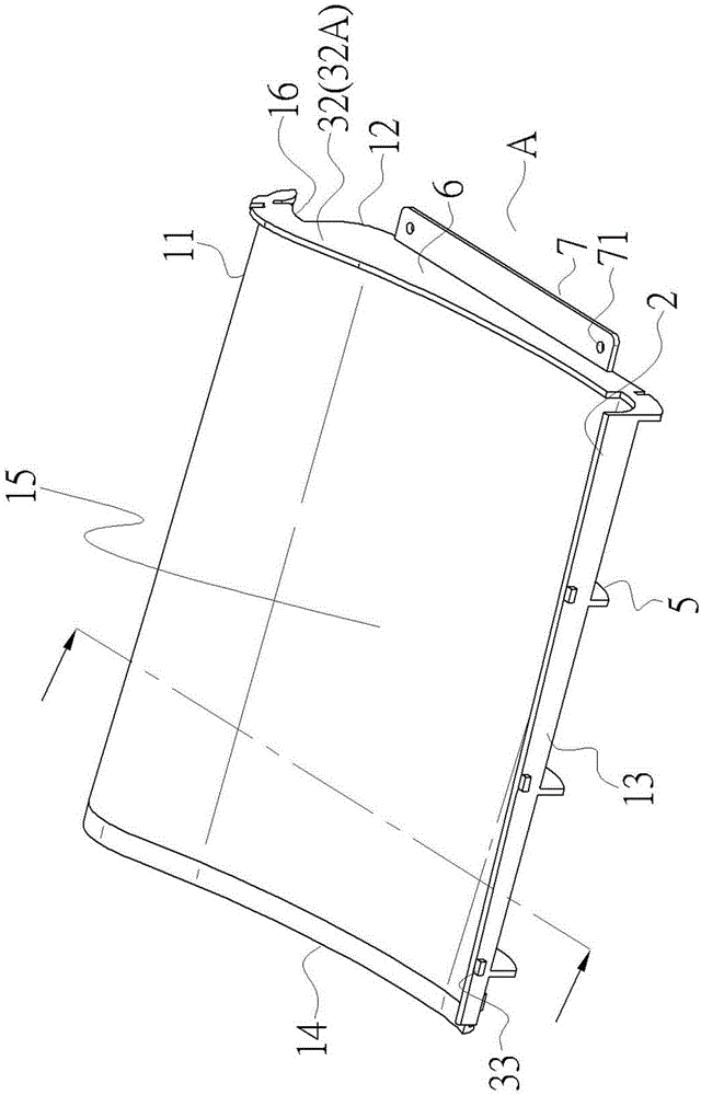
[0033] See figure 1 As shown, the present invention relates to a structure of a roof tile unit body, including:

[0034] A tile body 1:

[0035] See figure 1 Cooperate Picture 11 As shown, the tile body 1 is sequentially provided with a first to fourth edges 11, 12, 13, 14 in a clockwise direction, and the top surface of the tile body 1 faces the third edge from the first edge 11 13 is recessed inward to form a first concave arc surface 15, and the bottom surface of the tile body 1 is adjacent to the third edge 13 and is preferably recessed inwardly along the direction of the third edge 13 to form a second concave arc surface 16.

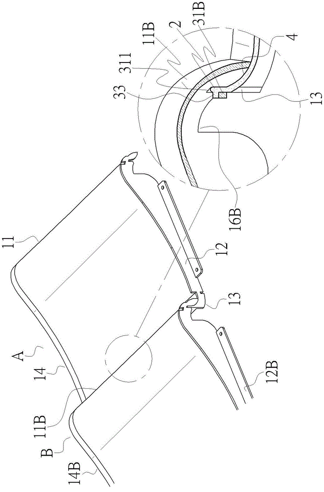
[0036] One wing piece 2:

[0037] See figure 1 Cooperate figure 2 and Picture 11 As shown, the fin 2 extends upward along the third edge 13, so t...


PUM


Abstract

The present invention relates to a structure of a roof tile unit. The roof tile unit mainly includes four edges, the top surface of the roof tile unit is inwardly recessed from one of the edges towards the opposite edge for forming a continuous arc-shaped surface, and the opposite edge is upwardly extended with a flap. Each of the edges is respectively formed with a connection member for allowing the roof tile unit to be combined with the other same roof tile unit. One of the edges of the roof tile unit is stacked upon the flap of the other same roof tile unit. Accordingly, with each of the connection members, the two same roof tile units are allowed to be mutually combined, so that plural roof tile units can form a roof. When one of the roof tile units is damaged, the damaged roof tile unit can be individually replaced without detaching and replacing the whole roof. Moreover, the flap is able to provide a blocking effect, so that rainwater is effectively prevented from entering the top end of a building from a gap formed between the two mutually connected roof tile units, thereby enhancing the rainwater blocking effect.

Description

Technical field [0001] The invention relates to a roof tile, in particular to the structure of a roof tile unit body. Background technique [0002] According to the fact, the tops of early buildings were mostly flat structures, and such flat structures were easily affected by factors such as aging of the waterproof layer and poor construction, which caused water leakage and water seepage. [0003] Therefore, roof tiles are used to pave the top of such buildings to form a slanted roof on both sides of the bulge in the middle. This structure can achieve: (1) Use the slope to pour out the rainwater on the roof to prevent rainwater from silting up. Problems such as water leakage and seepage. (2) The space enclosed by the roof tiles and the top of the building can guide the air to form convection, which has the effect of warming in winter and cooling in summer. (3) Through the shape and color of the roof tiles, the appearance of the building creates a varied and diverse architectural ...

Claims


Application Information

Patent Timeline
Patent Type & Authority Applications(China)
IPC IPC(8): E04D1/02E04D1/36
Inventor 蔡子良
Owner HUBEI XINXINLAN ENVIRONMENTAL PROTECTION TECH CO LTD
Why Eureka
Try Eureka