Closed low temperature compressed air energy storage system and method
What is AI technical title?
AI technical title is built by Patsnap AI team. It summarizes the technical point description of the patent document.
A technology of compressed air energy storage and air at room temperature, which is applied in the direction of variable volume pump components, liquid variable volume machinery, steam engine devices, etc., can solve problems such as strong environmental dependence, achieve broad application prospects, improve system efficiency, and improve The effect of energy storage efficiency
Active Publication Date: 2016-08-17
中储国能(北京)技术有限公司
View PDF5 Cites 19 Cited by
Summary
Abstract
Description
Claims
Application Information
AI Technical Summary
This helps you quickly interpret patents by identifying the three key elements:
Problems solved by technology
Method used
Benefits of technology
Problems solved by technology
However, most of the existing compressed air energy storage systems are open cycle systems, which must obtain storage working fluid from the environment and are highly dependent on the environment.
Method used
Image
Click on the blue label to locate the original text in one second.
Reading with bidirectional positioning of images and text.
Examples
Embodiment 1
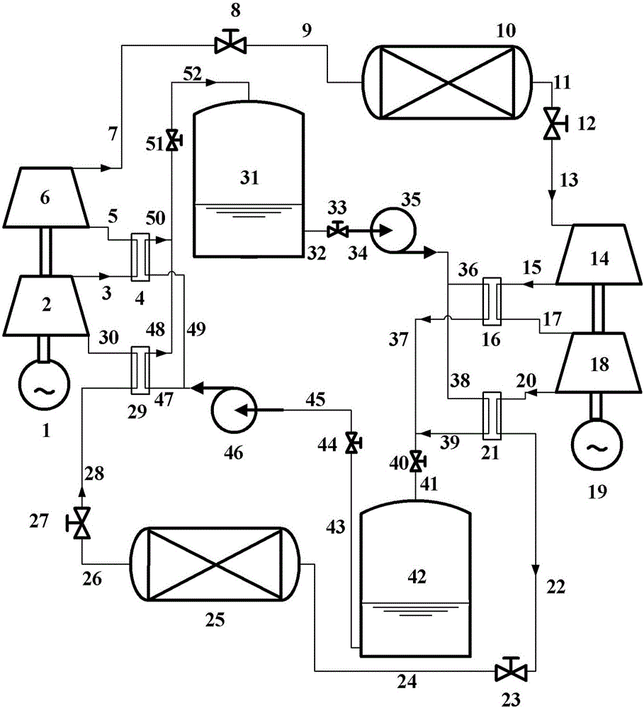
[0070] figure 1 Shown is Embodiment 1 of the closed low-temperature compressed air energy storage system of the present invention, which adopts two-stage compression, inter-stage cooling and two-stage expansion, and inter-stage heating. among them, figure 1 The reference signs in have the following meanings:
[0071] Motor 1, low pressure compressor 2, high pressure compressor 6, high pressure expander 14, low pressure expander 18, heat exchanger 4, 16, 21, 29, valve 8, 12, 23, 27, 33, 40, 44, 51 , Pipelines 3, 5, 7, 9, 11, 13, 15, 17, 20, 22, 24, 26, 28, 30, 32, 34, 36, 37, 38, 39, 41, 43, 45, 47, 48, 49, 50, 52, high pressure gas storage device 10, low pressure gas storage device 25, generator 19, normal temperature storage tank 31, low temperature storage tank 42, cryogenic pump 46, normal temperature pump 35, cold storage working medium and air.
[0072] The motor 1 is connected with the common drive shaft of the compressor unit, and the generator 19 is connected with the comm...
Embodiment 2
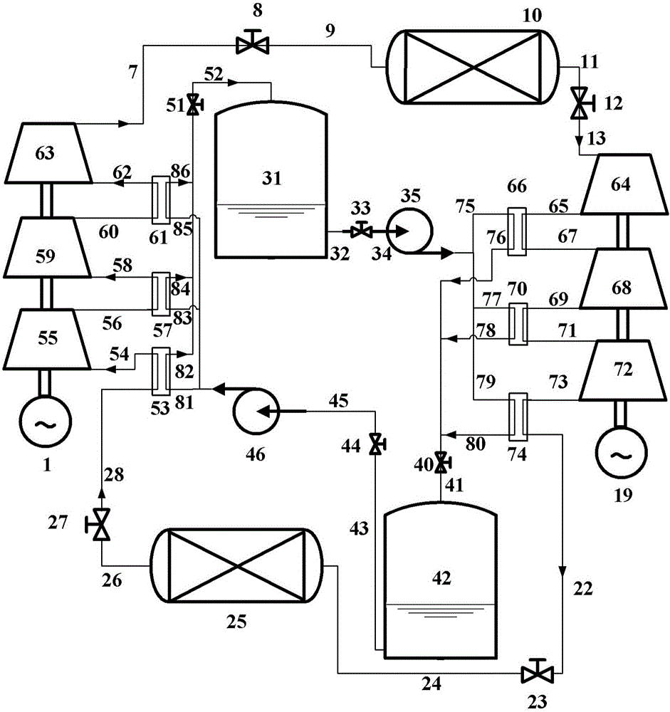
[0076] figure 2 Shown is embodiment 2 of the closed low-temperature compressed air energy storage system of the present invention. Its main structure is the same as that of embodiment 1, but it uses three-stage compression, inter-stage cooling, three-stage expansion, and inter-stage heating instead of embodiment 1. Two-stage compression, inter-stage cooling and two-stage expansion, inter-stage heating. among them, figure 2 The reference signs in have the following meanings:
[0077] Motor 1, low pressure compressor 55, medium pressure compressor 59, high pressure compressor 63, high pressure expander 64, medium pressure expander 68, low pressure expander 72, heat exchanger 53, 57, 61, 66, 70, 74, High pressure gas storage device 10, low pressure gas storage device 25, normal temperature storage tank 31, low temperature storage tank 42, cryogenic pump 46, normal temperature pump 35, valves 8, 12, 23, 27, 33, 40, 44, 51, pipeline 26, 28,54,56,58,60,62,7,9,11,13,65,67,69,71,73,...
PUM
Abstract
The invention provides a closed low temperature compressed airenergy storagesystem. The system is characterized in that a low temperature cold storage working medium performs heat exchange on normal temperature air in a first heat exchanger unit, a normal temperature cold storage working medium is output, and a compressor set is used for inputting air after heat exchange; a normal temperature storage tank is used for inputting and storing the normal temperature cold storage working medium; an expander set is used for inputting stored compressed air; the compressed air works on the expander set in the expander set to output expanded and cooled air; the normal temperature cold storage working medium performs heat exchange on the expanded and cooled air in a second heat exchanger unit and then is converted to a low temperature cold storage working medium; the expanded and cooled air is converted to normal temperature air after heat exchange; a low temperature storage tank is used for inputting the low temperature cold storage working medium to be stored and outputting the low temperature cold storage working medium to the first heat exchanger unit; a low pressure air storage device is used for inputting the normal temperature air to be stored and outputting the normal temperature air to the first heat exchanger unit. The energy storagesystem adopts two-loop closed circulation, so that the compressed air energy storage system does not transfer mass to the environment; therefore the application range of the energy storage system is widened and the dependence of the energy storage system on the environment is low.
Description
Technical field [0001] The invention relates to the technical field of electric energy storage, in particular to a closed low-temperature compressed air energy storage system and an energy storage method. Background technique [0002] In recent years, the peak-to-valley ratio of electricity load in my country has been increasing, and the installed capacity of renewable energy power generation such as wind energy and solar energy has gradually increased. Coupled with the development demand for distributed energy, the importance of electric energy storage technology has gradually emerged. At present, electric energy storage technologies include pumped water energy storage, compressed air energy storage, battery energy storage, flywheel energy storage, super capacitors, etc., while compressed air energy storage is comparable to pumped water energy storage in terms of capacity and construction costs, making it a One of the competitive power storage technologies. However, most of the...
Claims
Application Information
Patent Timeline
Application Date:The date an application was filed.
Publication Date:The date a patent or application was officially published.
First Publication Date:The earliest publication date of a patent with the same application number.
Issue Date:Publication date of the patent grant document.
PCT Entry Date:The Entry date of PCT National Phase.
Estimated Expiry Date:The statutory expiry date of a patent right according to the Patent Law, and it is the longest term of protection that the patent right can achieve without the termination of the patent right due to other reasons(Term extension factor has been taken into account ).
Invalid Date:Actual expiry date is based on effective date or publication date of legal transaction data of invalid patent.

