internal combustion engine with turbine

A technology of internal combustion engines and turbines, applied in the direction of internal combustion piston engines, combustion engines, engine components, etc., can solve the problems of unsatisfactory operation behavior, poor efficiency, etc., achieve low inertia, high efficiency, and improve the effect of operation behavior

Active Publication Date: 2020-06-09
FORD GLOBAL TECH LLC
View PDF3 Cites 0 Cited by
  • Summary
  • Abstract
  • Description
  • Claims
  • Application Information

AI Technical Summary

Problems solved by technology

However, the main disadvantage is the relatively poor efficiency of the relatively large turbine, which during operation operates primarily with an exhaust gas mass flow that is less than what can actually be handled
Such a turbine exhibits an extremely unsatisfactory operating behavior at small exhaust mass flows

Method used


Image

  • internal combustion engine with turbine
  • internal combustion engine with turbine
  • internal combustion engine with turbine

Examples


Embodiment Construction

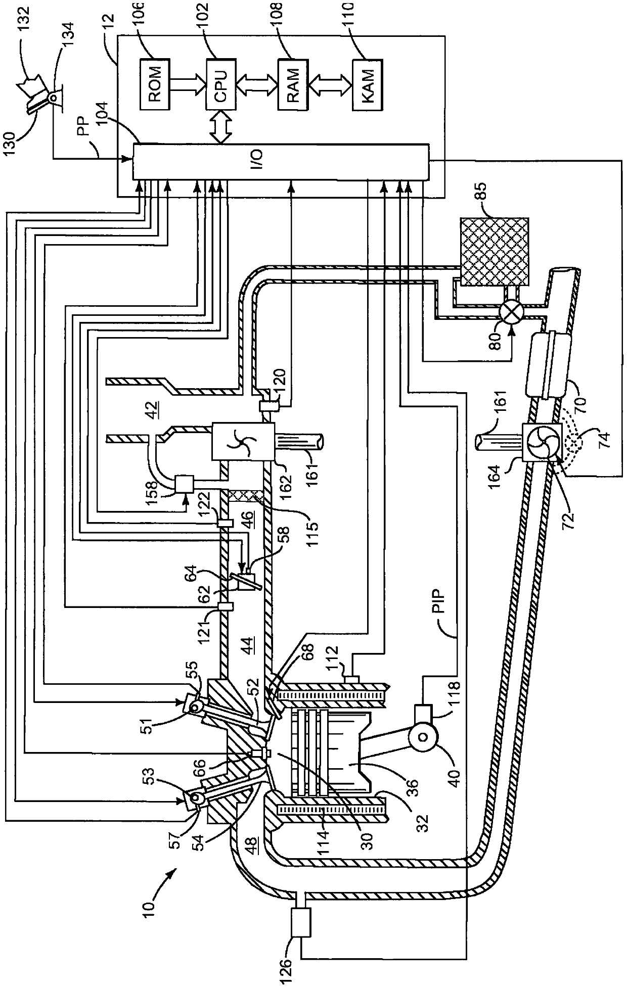
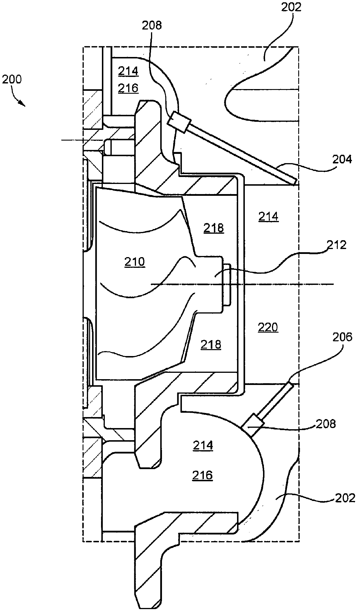
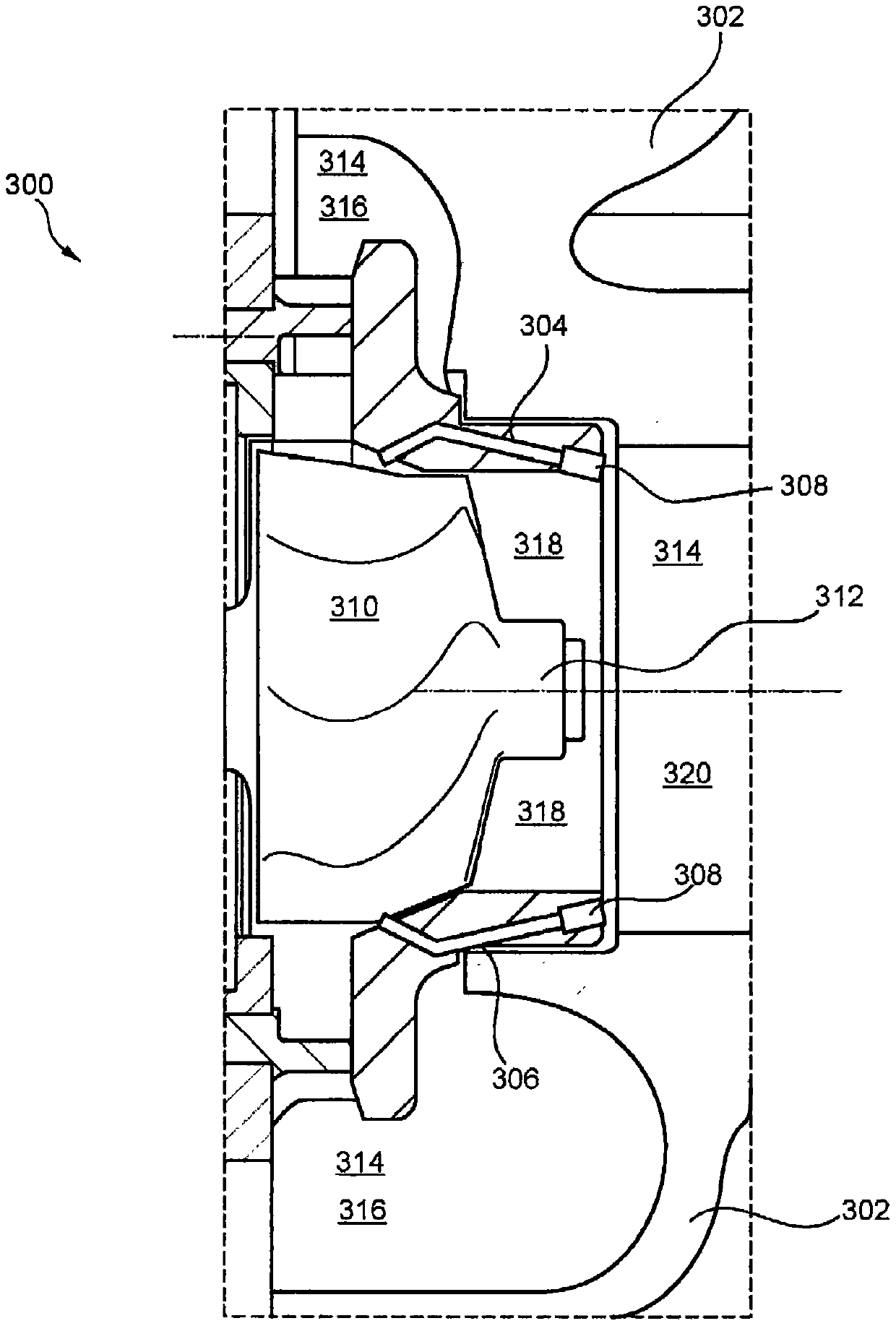
[0023] The following description relates to systems and methods for controlling a turbine within an internal combustion engine. In particular, this specification relates to the control of such figure 2 with image 3 The respective turbines of the turbine system 200 and the turbine system 300 may include at least one overpressure line in the turbine housing. in addition, Figure 2-3 Turbine systems can include an overpressure line equipped with a self-regulating pressure valve that opens automatically when the pressure in the inlet region of the turbine begins to exceed a certain pre-definable pressure. figure 1 An example internal combustion engine including a turbine is shown.

[0024] figure 1 The turbine 164 in the first embodiment of the internal combustion engine turbine 200 is exemplified in figure 2 further explained in . In this example embodiment, overpressure lines 204 , 206 may be provided that branch off from an exhaust gas guiding duct 214 , which may be l...


PUM


Abstract

Methods and systems are provided for controlling a turbine within an internal combustion engine. In one example, a turbine system within an internal combustion engine may include at least one turbine with a housing that may further include at least one impeller mounted on a rotatable shaft, inlet and outlet regions, and at least one overpressure line including a self-controlling valve for controlling the flow of exhaust gas.

Description

[0001] Cross References to Related Applications [0002] This application claims priority from German Patent Application No. 102015202224.2 filed on February 9, 2015, the entire content of which is hereby incorporated by reference for all purposes. technical field [0003] The present description generally relates to methods and systems for controlling a turbine within an internal combustion engine. Background technique [0004] An internal combustion engine has a cylinder block and at least one cylinder head, which are connected to one another to form cylinders of the engine. During charge exchange, combustion gases are exhausted via an outlet port and charge the cylinders via an intake port. In order to control the charge exchange, an internal combustion engine requires a control element such as a poppet valve and an actuation device for actuating the control element. The valve drive mechanisms required for the movement of the valves and the valves themselves are referre...

Claims


Application Information

Patent Timeline
Patent Type & Authority Patents(China)
IPC IPC(8): F02B37/18
CPCF02B37/18F01D17/105F02B37/183F02B39/16F02B2039/166F02C6/12Y02T10/12
Inventor J·克默林H·M·金德尔V·斯米利亚诺夫斯基F·A·萨默候夫A·库斯克F·文德利希
Owner FORD GLOBAL TECH LLC
Why Eureka
Try Eureka