
A high-pressure natural gas injector calibration device and method thereof

The technology of a calibration device and calibration method is applied in the field of internal combustion engine research, which can solve the problems of inability to calibrate intermittent jets of high-pressure gas injectors and large errors, and achieve the effects of safety assurance, reasonable structural design and strong flexibility.

Inactive Publication Date: 2018-06-26
JIANGSU UNIV
View PDF6 Cites 0 Cited by
  • Summary
  • Abstract
  • Description
  • Claims
  • Application Information

AI Technical Summary

Problems solved by technology

The patent application number 201510528149.1 proposes a gas flow calibration method with adjustable temperature and pressure. This method realizes continuous adjustment of pressure and temperature through multi-stage pressure regulating devices, heaters and condensers, and measures the Accumulated flow to achieve gas flow calibration at different temperatures and pressures. This method is suitable for gas flow calibration in industrial low-pressure constant gas delivery pipelines, and cannot be calibrated for intermittent jets of high-pressure gas injectors.
In the literature (FUEL, 160(2015) 24-34), Iman Erfan et al., in the experimental research on the jet characteristics of natural gas injection, measured the mass reduction of natural gas before and after the experiment by placing the natural gas tank on an electronic balance. And according to the number of injections, the single injection volume of the natural gas injector is calculated. This method is simple to operate, but the error is large, and a high-precision electronic balance is required

Method used


Image

  • A high-pressure natural gas injector calibration device and method thereof
  • A high-pressure natural gas injector calibration device and method thereof
  • A high-pressure natural gas injector calibration device and method thereof

Examples


Embodiment approach

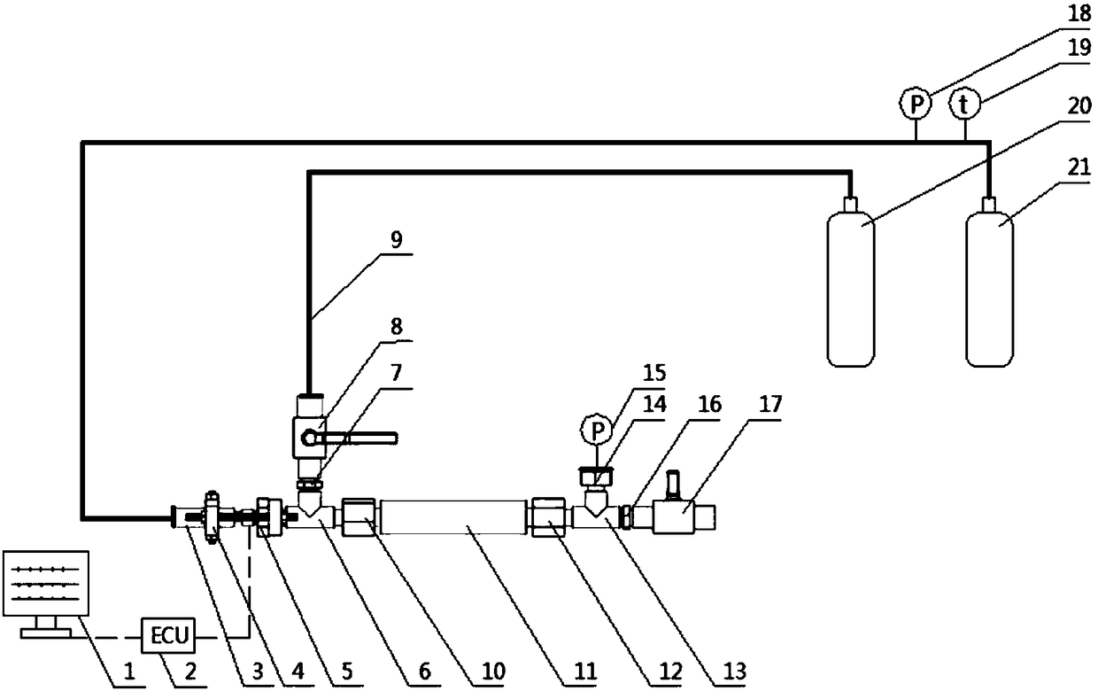
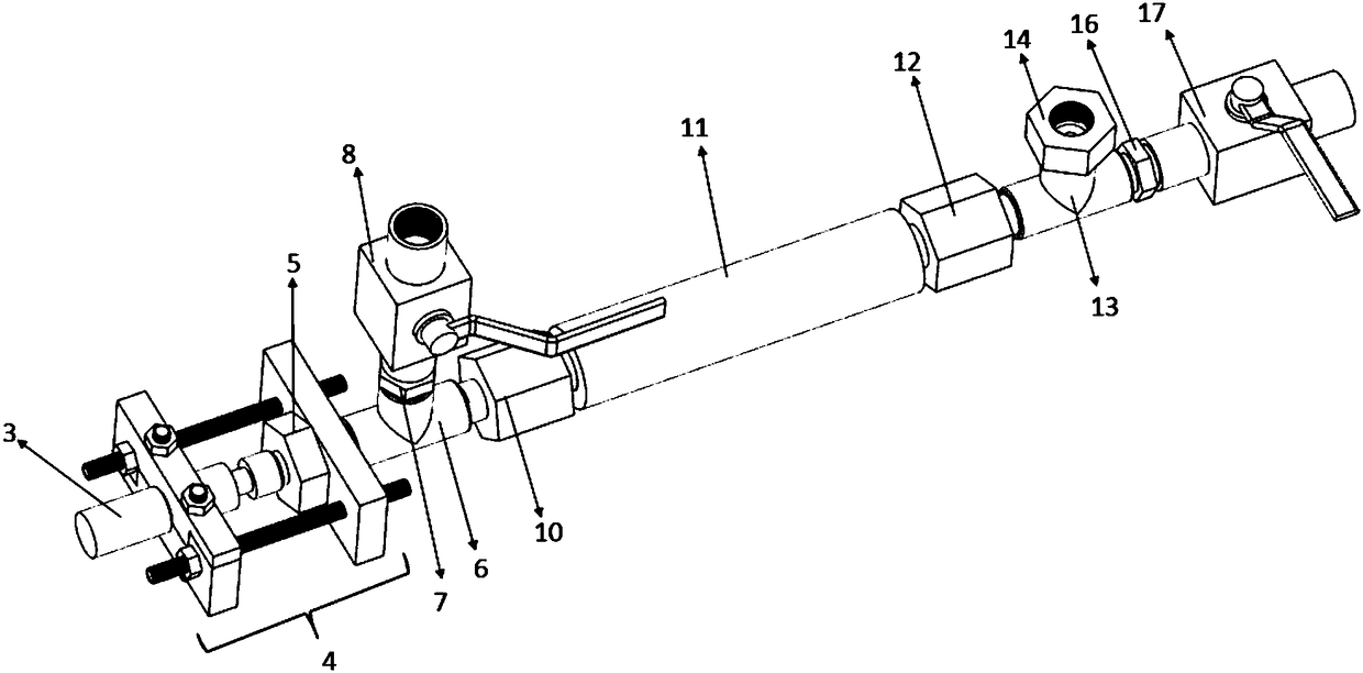
[0030] figure 1 and figure 2 Shown is an embodiment of the high-pressure natural gas injector calibration device of the present invention, the high-pressure natural gas injector calibration device includes a computer 1, injector control system ECU2, natural gas injector 3, calibration components, gas supply system and nitrogen 20 bottles.

[0031] The calibration assembly includes a natural gas injector mount 5, a first three-way piece 6, a cylindrical container 11, a second three-way piece 13, a second valve 17, a pressure sensor mount 14 and a first pressure sensor 15. The gas supply system includes a natural gas tank 21. One end of the natural gas injector 3 is connected to the natural gas tank 21 through a high-pressure metal hose, and the other end is connected to one end of the natural gas injector mounting base 5 through a clamp 4, and the other end of the natural gas injector mounting base 5 is threaded to the second The first port of a three-way piece 6 is in seal...


PUM


Abstract

The invention belongs to the research field of internal combustion engines and provides a calibration device and method for a high-pressure natural gas injector. The calibration device for the high-pressure natural gas injector comprises a computer, an injector control system ECU, the natural gas injector, calibration assemblies and a gas supplying system. One end of the natural gas injector is connected with a nature gas tank of the gas supplying system through a high-pressure metal hose, and the other end of the natural gas injector is installed on the calibration assemblies through a fixture. The calibration device is overall sealed. The injector control system ECU controls the natural gas injector to be opened and closed. According to the calibration device and method for the high-pressure natural gas injector, the pressure change value of gas in the device when the natural gas injector operates within a certain time is measured, and then the one-time injection gas quantity of the injector is worked out, so that important experimental data are provided for the development of a natural gas engine; a combined method is adopted by the calibration assemblies in the design, and the calibration assemblies can be freely assembled according to the requirement and are high in flexibility; and the gas tightness and the safety of the calibration device for the high-pressure natural gas injector are ensured through the reasonable structural design and precise machining.

Description

technical field [0001] The invention belongs to the field of internal combustion engine research, and in particular relates to a calibration device and method for a high-pressure natural gas injector. Background technique [0002] With the increasing global energy crisis and environmental pollution. An effective way to solve the problem of diesel exhaust pollution is to use alternative fuels, including biomass fuel, LPG and natural gas. As a natural gas, shale gas can solve human energy problems for at least the next 50 years. According to estimates by the U.S. Energy Information Administration, China's shale gas reserves are larger than those of the United States, accounting for about 20% of the world's total reserves, ranking first in the world. It can be seen that the application of natural gas will have great development prospects in the future. [0003] The natural gas engine has obvious economic benefits and excellent environmental performance, making it the focus o...

Claims


Application Information

Patent Timeline
Patent Type & Authority Patents(China)
IPC IPC(8): F02M65/00
CPCF02M65/001
Inventor 谭小强邵长胜王谦何志霞韩丹
Owner JIANGSU UNIV
Learn More