
A design method for blunt trailing edge of wind turbine airfoil based on geometric transformation

A technology of geometric transformation and design method, which is applied to wind turbines, wind turbines, mechanical equipment and other directions that are consistent with the wind direction to achieve the best aerodynamic performance improvement effect, prevent the reduction of the effect, and improve the calculation accuracy.

Active Publication Date: 2018-06-15
TIANJIN POLYTECHNIC UNIV
View PDF6 Cites 0 Cited by
  • Summary
  • Abstract
  • Description
  • Claims
  • Application Information

AI Technical Summary

Problems solved by technology

[0004] Although many researchers have done a lot of research on the influence of the blunt trailing edge modification on the aerodynamic performance of the airfoil, the use of geometric transformations to express the blunt trailing edge modification line and analyze the optimal trailing edge thickness has not involved

Method used


Image

  • A design method for blunt trailing edge of wind turbine airfoil based on geometric transformation
  • A design method for blunt trailing edge of wind turbine airfoil based on geometric transformation
  • A design method for blunt trailing edge of wind turbine airfoil based on geometric transformation

Examples


Embodiment

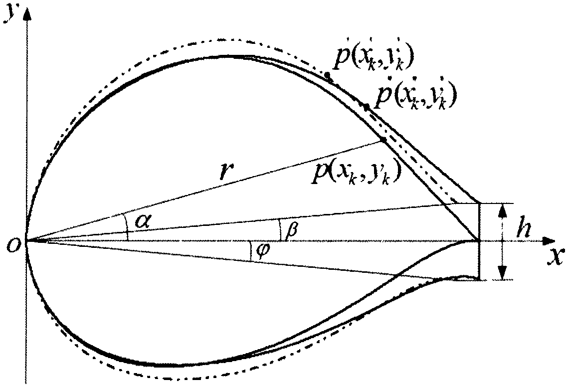
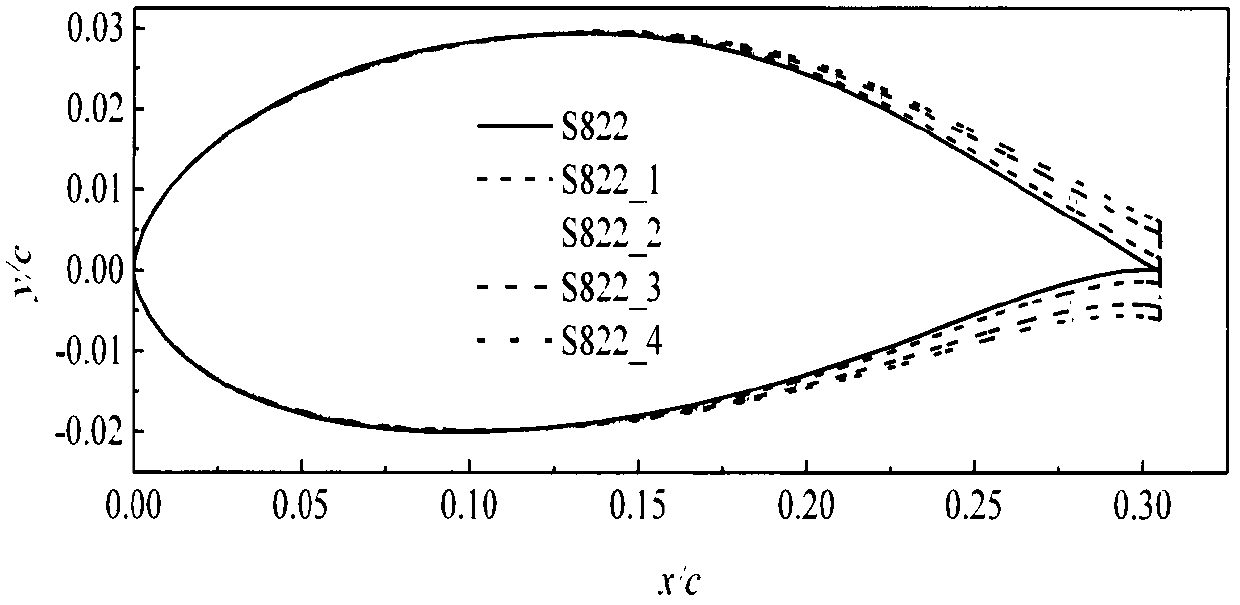
[0074] 1. The S822 airfoil is widely used in the main power generation area of ​​wind turbine blades, with a maximum relative thickness of 16% at 39.2%c and a maximum relative camber of 1.92% at 59.5%c. When the thickness of the trailing edge is 1.0%c, 2.0%c, 3%c and 4%c respectively, according to the distribution ratio of the upper and lower thickness of the center arc is 2:2, the modified formula (6) and (7) form the wing Type S822 blunt trailing edge modification line ( figure 2 ), and use S822_1, S822_2, S822_3, S822_4 to represent the above four kinds of trailing edge thickness respectively.

[0075] 2,

[0076] (1) Computing Grid

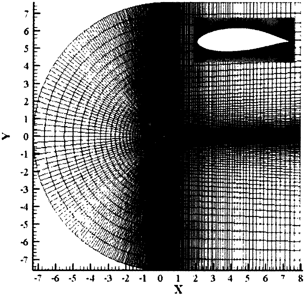
[0077] The geometric model, computational domain and mesh of the airfoil were generated by using the Fluent pre-processing software Gambit ( image 3 ). The calculation domain consists of a semicircle with a diameter of 50c and a rectangle with a length of 50c and a width of 25c. The airfoil is located in the center of the semicircle to e...


PUM


Abstract

The invention discloses a method for designing wind turbine airfoil profile blunt trailing edges based on geometric transformation. The method includes the following steps that a blunt trailing edge airfoil profile mathematical expression is established through combination of coordinate revolution transformation and scaling of x-coordinate and y-coordinate coefficients; the trailing edge thicknesses of an S822 airfoil profile are increased symmetrically; the aerodynamic performance for modification of the blunt trailing edges of different trailing edge thicknesses are worked out through the k-w SST turbulence model numerical value; and the influence of the trailing edge thicknesses on the airfoil profile lifting coefficient, the airfoil profile dragging coefficient and the lifting-dragging ratio is analyzed, the optimal trailing edge thickness for modification of the blunt trailing edges is obtained, and accordingly the method for designing the wind turbine airfoil profile blunt trailing edges based on geometric transformation is achieved. By means of the method, the airfoil profiles of the wind turbine blunt trailing edges have the optimal trailing edge thickness, namely 2% of the chord length, the wind power capture capacity of a wind turbine is better improved, and the cost for power generation is reduced.

Description

technical field [0001] The invention belongs to the technical field of airfoil modification and aerodynamic performance calculation, and in particular relates to a method for designing a blunt trailing edge of a wind turbine airfoil based on geometric transformation using computational fluid dynamics. Background technique [0002] Wind energy is a renewable energy with large-scale development and industrial development prospects. Wind turbine blades are key components for capturing wind energy in wind energy utilization. Wind turbines installed in alpine and coastal areas often encounter weather conditions of low temperature, high humidity, freezing rain or snow. At this time, ice accumulation will appear on the surface of the blades. Ice accumulation will change the aerodynamic shape of the blade and increase the surface roughness, resulting in a decrease in the wind energy conversion rate; ice accumulation will also increase the static and dynamic load of the blade and th...

Claims


Application Information

Patent Timeline
Patent Type & Authority Patents(China)
IPC IPC(8): F03D1/06
CPCF03D1/0608Y02E10/72
Inventor 张旭李伟刘海龙刘安宁
Owner TIANJIN POLYTECHNIC UNIV
Learn More