Design method of blade power-increasing trailing edge flap

A design method and flap technology, applied in design optimization/simulation, mechanical equipment, and wind turbines consistent with the wind direction, etc., can solve problems such as lack of flap design methods, achieve reduced induced drag loss, high accuracy, The effect of increasing the ability to capture wind energy

Pending Publication Date: 2022-03-08
华能湖北新能源有限责任公司 +1
View PDF0 Cites 0 Cited by
  • Summary
  • Abstract
  • Description
  • Claims
  • Application Information

AI Technical Summary

Problems solved by technology

[0005] Aiming at the lack of a clear and detailed flap design method in the prior art, the present invention proposes a design method for blade power-enhancing trailing edge flaps

Method used


Image

  • Design method of blade power-increasing trailing edge flap
  • Design method of blade power-increasing trailing edge flap
  • Design method of blade power-increasing trailing edge flap

Examples


Embodiment 1

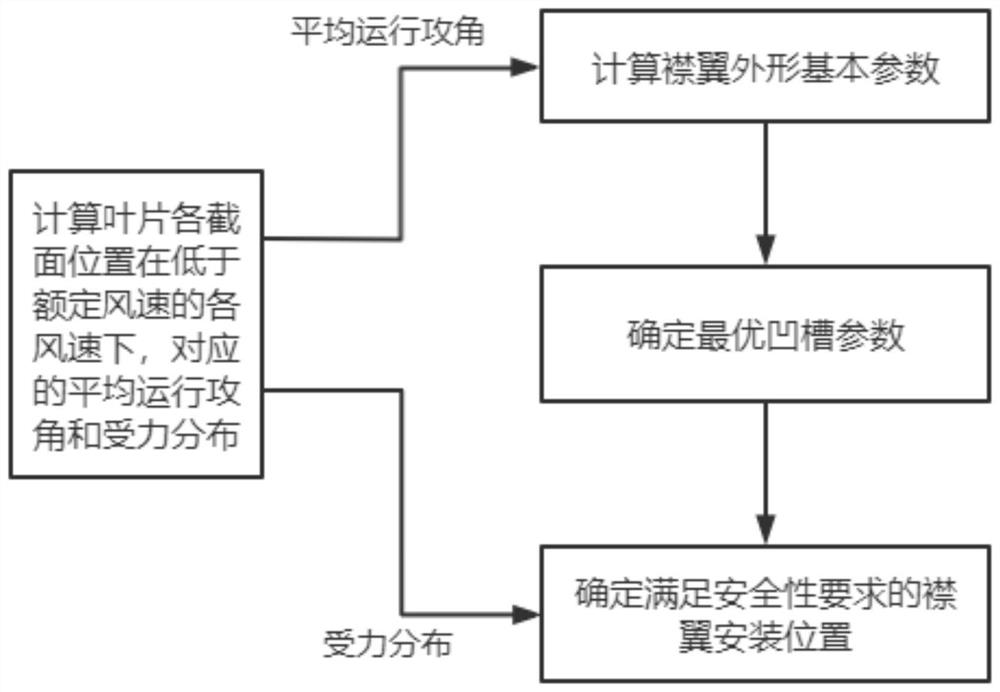
[0056] Such as image 3 As shown, a blade power-enhancing trailing edge flap design method, the steps include:

[0057] Step 1: Calculate the corresponding average operating angle of attack and force distribution of each cross-section position of the blade at each wind speed lower than the rated wind speed;

[0058] Step: 2: Design and calculate the flap profile and parameters by the average operating angle of attack;

[0059] Step 3: Calculate the optimal groove parameters through the shape and parameters of the flap;

[0060]Step 4: Determine the flap installation position that meets the safety requirements through the optimal groove parameters and the force distribution in step 1.

[0061] Specific steps such as Figure 4 shown.

[0062] Described step 1 comprises as follows:

[0063] The average operating angle of attack and force distribution corresponding to each section position of the blade at each wind speed lower than the rated wind speed are calculated by GH Bl...

Embodiment 2

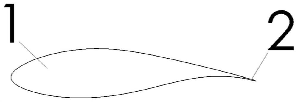
[0096] Taking the NACA63421 airfoil as an example, the external dimensions of the flap and the groove are designed and calculated according to the content of the present invention. The lift calculation results of different shapes of Rfoil are as follows: Figure 6 As shown, in the figure Mach=0.15, Re=3E6. The calculations of flap down angle, thickness, and wedge shape are the same as in Embodiment 1. The lift-to-drag ratio of the airfoil varies with the flap length as follows: Figure 7 shown.

[0097]

[0098]

[0099]

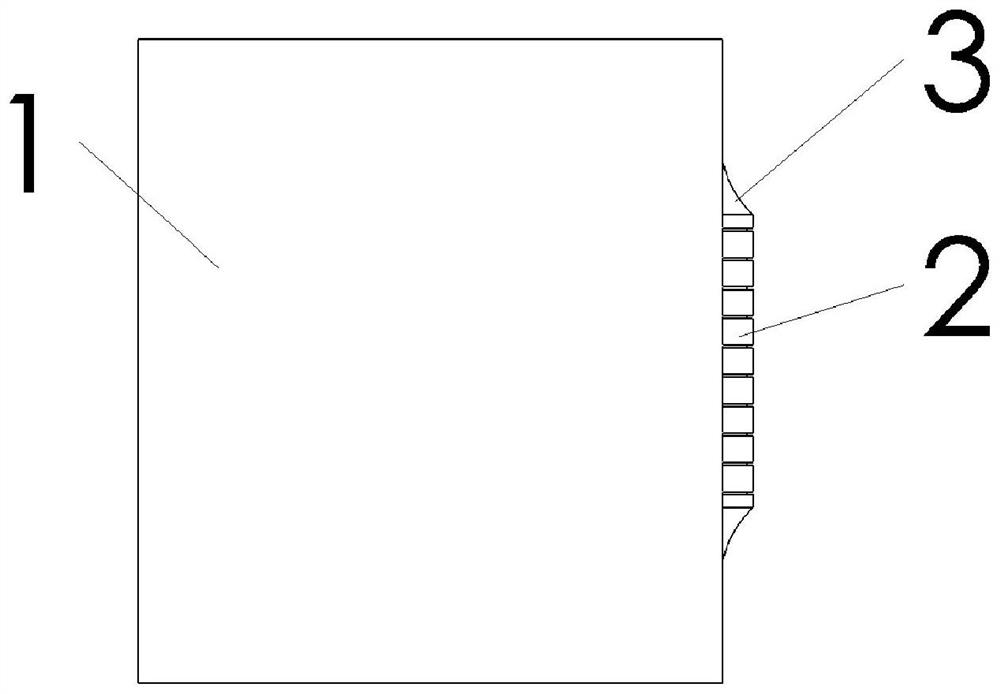
[0100] Model the determined flap dimensions and NACA63421 airfoil structure in 3D modeling software, design the surface groove size, and perform grid division, steady-state calculation and transient calculation iterations through professional fluid calculation software, and get Optimal groove parameters and aerodynamic effects.

[0101] The final calculation results show that after the NACA63421 airfoil is equipped with flaps with grooves, the b...


PUM


Abstract

The invention relates to the field of wind power generation, in particular to a blade power-increasing trailing edge flap design method, which comprises the following steps of: calculating corresponding average operation attack angles, optimal pitch angles and stress distribution of each section of a blade at different wind speeds lower than a rated wind speed; flap parameters are added to the blade airfoil, and the optimal flap parameters are judged based on the judgment basis including the average operation attack angle and the optimal pitch angle; for the airfoil profile with the optimal flap parameters, modeling and adding groove parameters, and carrying out simulation calculation to obtain optimal groove parameters; and for the airfoil profile with the optimal groove parameters, the flap mounting position meeting the safety requirement is determined based on the stress distribution. For the airfoil main body with the relative thickness of 16-25%, close to the blade tip area, of the outer side of the blade in the spanwise direction, the lift coefficient and the lift-drag ratio of the airfoil main body can be well improved, and the good power increasing and noise reducing effects are achieved.

Description

technical field [0001] The invention relates to the field of wind power generation, in particular to a design method for blade power-increasing trailing edge flaps. Background technique [0002] Wind turbine blades are the main components of wind turbines to capture wind energy, and there are many factors that determine the aerodynamic performance of blades, such as aerodynamic shape, airfoil, and structure. The design of the blade is based on the best aerodynamic performance, and then through iterative optimization, the structural shape of the blade is optimized to meet the requirements of the blade's structural safety, noise control, and trailing edge shedding vortex control when the unit is running. The blade sacrifices some aerodynamic performance. [0003] There are many ways to increase the power of the blades. The common ones are vortex generators that delay or suppress the stall, Gurney flaps and spoilers that improve the shedding vortex at the trailing edge and inc...

Claims


Application Information

Patent Timeline
IPC IPC(8): G06F30/17G06F30/20F03D1/06G06F119/14
CPCG06F30/17G06F30/20F03D1/0675G06F2119/14Y02E10/72
Inventor 张林伟虞小兵蔡安民陈浩彭阁李林川林伟荣李力森李媛许扬金强
Owner 华能湖北新能源有限责任公司
Why Eureka
Try Eureka