Tristable press linkage switching mechanism
A switching mechanism and tri-stable technology, applied in the direction of engine components, mechanical equipment, valve details, etc., can solve the problems that the switching mechanism is difficult to meet the use requirements, difficult to switch positions, complex structure of the switching mechanism, etc., to achieve simple structure and easy switching , the effect of expanding the scope of application
- Summary
- Abstract
- Description
- Claims
- Application Information
AI Technical Summary
Problems solved by technology
Method used
Image
Examples
Embodiment 1
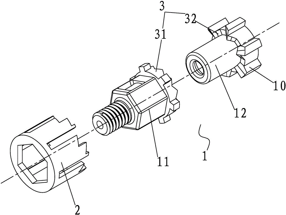
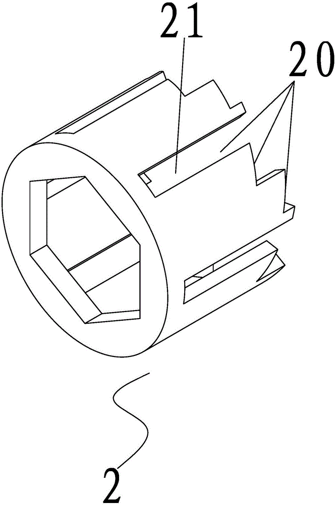
[0027] Embodiment one: if Figure 1 to Figure 4 As shown, a three-stable pressing linkage switching mechanism described in this embodiment includes two parts: a pressing drive unit 1 and a limiting component 2;
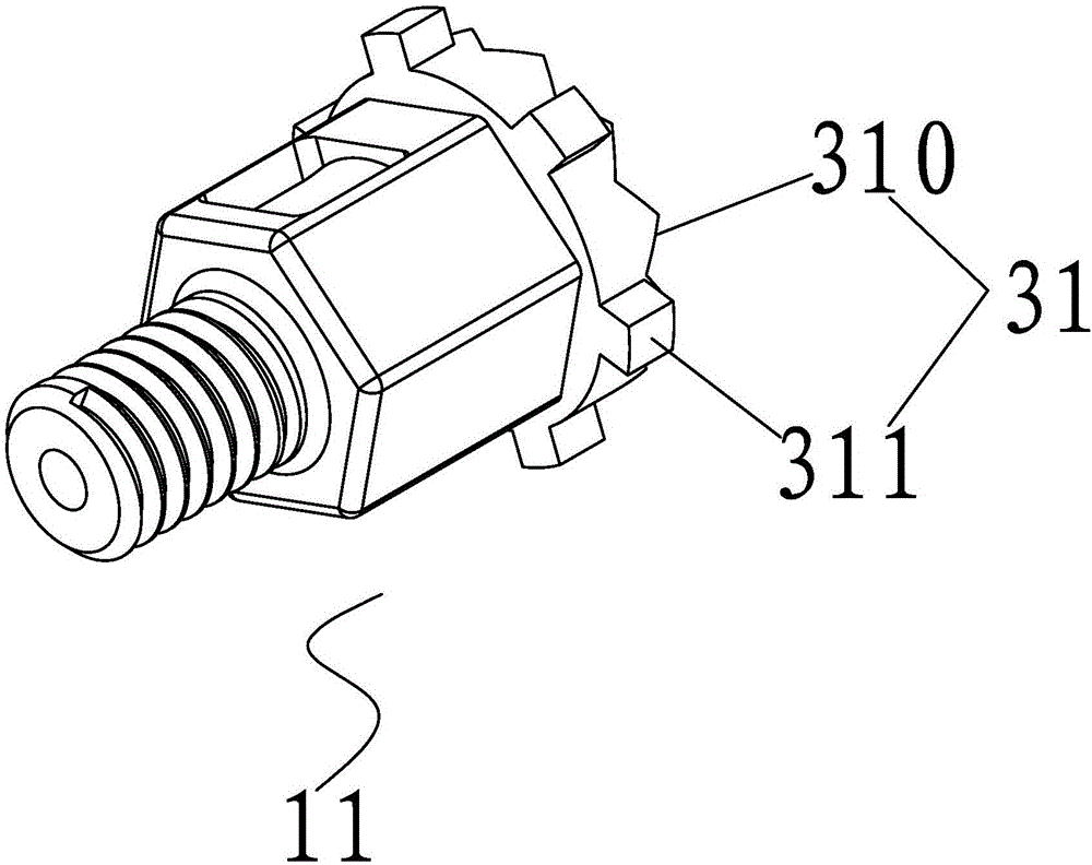
[0028] Pressing the drive unit 1, which is set separately, it includes a pressing ejector 11 and a rotating hook 12; the pressing ejector 11 and the rotating hook 12 are socketed and matched to form a pressing and rotating structure 3;
[0029] The pressing and rotating structure 3 includes a resisting part 31 and a rotating passive part 32; the rotating passive part 32 is formed on the outer periphery of the rotating hook 12, and the resisting part 31 is arranged at the end of the pressing and ejecting part 11, and match with the rotating passive part 32;
[0030] The rotating passive part 32 in the rotating hook 12 is also provided with a switching limit structure 4 that cooperates with the abutting part 31; the switching limit structure 4 includes a hooking limit ...
Embodiment 2
[0034] Embodiment two: if Figure 5 to Figure 6 The same parts of this embodiment shown in this embodiment are not repeated here. The three-stable pressing linkage switching mechanism described in this embodiment includes two parts: a pressing drive unit 1 and a limiting component 2;
[0035] Press the driving unit 1, a guide slide groove 12 is provided on its outer circumference, and a limit track 22 with the stop portion 20 is also formed on the limit member 2; a limit slide is also provided in the limit track 22 The bead 5 is slidably arranged on the chute and the limit track 22;
[0036]The limit sliding ball 5 includes a sliding part 51 and a matching part 52, the matching part 52 is placed in the guide chute 12; the sliding part 51 is placed in the limit track 22, and along the limit track 22 form a cyclic displacement;
[0037] Working principle: Press the driving unit 1 to move and move, and the limit sliding ball 5 in the guide chute 12 will move along the limit tra...
PUM
 Abstract
Description
Claims
Application Information
 - R&D
- Intellectual Property
- Life Sciences
- Materials
- Tech Scout
- Unparalleled Data Quality
- Higher Quality Content
- 60% Fewer Hallucinations
Browse by: Latest US Patents, China's latest patents, Technical Efficacy Thesaurus, Application Domain, Technology Topic, Popular Technical Reports.
© 2025 PatSnap. All rights reserved.Legal|Privacy policy|Modern Slavery Act Transparency Statement|Sitemap|About US| Contact US: help@patsnap.com


