In-field calibration device of pendulum type impact wave pressure sensor

A technology of pressure sensor and on-site calibration, which is applied in the direction of calibration/testing of force/torque/power measuring instruments, measuring devices, instruments, etc., which can solve problems such as multiple blows, pressure waveform differences, and no guidance, so as to prevent secondary Impact, easy transportation, light weight effect

Active Publication Date: 2016-08-17
南京卓砾智测控技术有限公司
View PDF11 Cites 18 Cited by
  • Summary
  • Abstract
  • Description
  • Claims
  • Application Information

AI Technical Summary

Problems solved by technology

However, the peak value of the pressure pulse generated by the existing drop hammer hydraulic calibration device is greater than 10MPa, and to achieve a pressure in the range of 0.1MPa to 10MPa, the calibration device must adopt a secondary hammer scheme, and the secondary hammer release and hammer connection cannot be like One-time hammer can realize the function of automatic hammer connection, and there is no guide, which may lead to the possibility of eccentricity and multiple strikes when the hammer body hits the precision piston, and the generated pressure waveform and semi-sine waveform are very different.
Secondly, because the pressure peak generated by the drop hammer hydraulic calibration device is relatively large, even reaching the GPa level, the structure of the drop hammer hydraulic calibration device is complex and bulky, and it is not suitable for field calibration

Method used


Image

  • In-field calibration device of pendulum type impact wave pressure sensor
  • In-field calibration device of pendulum type impact wave pressure sensor
  • In-field calibration device of pendulum type impact wave pressure sensor

Examples


Embodiment Construction

[0014] Below in conjunction with accompanying drawing and specific embodiment the present invention is described in further detail:

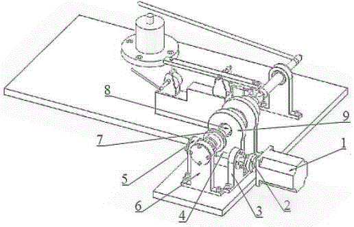
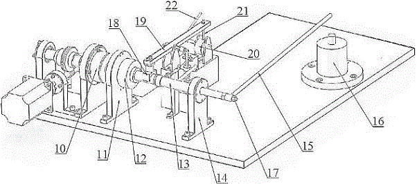
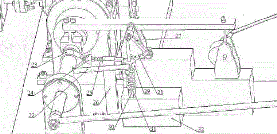
[0015] The invention provides a pendulum-type shock wave pressure sensor on-site calibration device. The calibration device is based on the principle of hydraulic calibration. The pendulum hits the pressure-making oil cylinder to generate a half-sine pressure pulse with a peak value ranging from 0.1MPa to 10MPa, thereby realizing a shock wave pressure sensor. on-site calibration.

[0016] The present invention as figure 1 -3 mainly includes: stepper motor 1, coupling 2, worm shaft front bearing seat 3, worm shaft 4, worm shaft rear bearing seat 5, worm wheel shaft front bearing seat 6, worm wheel 7, worm wheel shaft 8, worm wheel Shaft rear bearing seat 9, electromagnetic clutch 10, swing rod shaft front bearing seat 11, rotary encoder 12, swing rod shaft 13, swing rod shaft rear bearing seat 14, swing rod 15, pressure making cylinder 16, nut 1...


PUM


Abstract

In the application, a stepping motor is connected with a worm rod shaft; a worm wheel is mounted on a worm wheel shaft; an electromagnetic clutch is arranged on a rear bearing seat of the worm wheel shaft and is connected with the worm wheel shaft and a pendulum rod shaft; a rotary encoder is arranged on a front bearing seat of the pendulum rod shaft; the rotary encoder and the pendulum rod shaft are mounted together; a pendulum rod is mounted at the tail end of the pendulum rod shaft; a brake block is arranged on the rotary encoder and is mounted at one end of a brake pendulum rod; an eccentric wheel slide block is arranged at the other end of the brake pendulum rod; an eccentric wheel is arranged under the eccentric wheel slide block; one side of the eccentric wheel is connected with an eccentric wheel handle; the brake block is provided with a cam; a cam slide block is mounted on a cam slide block base; the brake pendulum rod is provided with a crank; the crank is connected with a connecting rod; a slide block is mounted at the other end of the connecting rod and is also mounted on a slide block guide rod; and a pressure production oil cylinder is arranged at the other end of the pendulum rod. According to a calibration device provided by the invention, the pressure production oil cylinder is impacted through a pendulum to generate half-sine pressure pulse with a peak value range of 0.1MPa-10MPa, so that in-field calibration of an impact wave pressure sensor is realized.

Description

technical field [0001] The invention relates to the field of measurement and calibration equipment, in particular to a field calibration device for a pendulum-type shock wave pressure sensor. Background technique [0002] During the shock wave pressure test, on the one hand, in order to suppress or reduce the parasitic effect, it is necessary to take necessary protective measures for the sensor, such as heat insulation, shockproof, and shock resistance, resulting in the occurrence of equivalent mass or equivalent stiffness of the actual sensor components. Variety. On the other hand, the sensitivity of the sensor will shift after long-term use, resulting in great uncertainty in the working characteristic parameters of the shock wave pressure test system. Therefore, it is essential to calibrate the measurement system before the actual shock wave stress test. [0003] For the ICP or piezoelectric high-resistance output sensors commonly used in shock wave pressure testing, sin...

Claims


Application Information

Patent Timeline
Patent Type & Authority Applications(China)
IPC IPC(8): G01L25/00
CPCG01L25/00
Inventor 孔德仁徐春冬江剑许兰涛
Owner 南京卓砾智测控技术有限公司
Why Eureka
Try Eureka