
A device and method for measuring the electrowetting effect of micro-droplets

A micro-droplet and electro-wetting technology, applied in the direction of measuring devices, surface/boundary effects, instruments, etc., can solve the problems of complex contact angle detection methods of micro-droplet electro-wetting effect and the influence of needle-shaped electrodes, and solve the problem of easy detachment Electrode problems, improved measurement accuracy, and low-cost effects

Active Publication Date: 2019-03-12
NANJING UNIV OF POSTS & TELECOMM
View PDF8 Cites 0 Cited by
  • Summary
  • Abstract
  • Description
  • Claims
  • Application Information

AI Technical Summary

Problems solved by technology

[0007] Purpose of the invention: To propose a device and method suitable for measuring the contact angle of the electro-wetting effect of micro-droplets, which is used to solve the problem of complex detection methods of the contact angle of the electro-wetting effect of micro-droplets and the shape of the contact angle of the perfect liquid surface by the needle-shaped electrode Influence and other issues, so that the measurement process is simplified and the measurement accuracy is improved

Method used


Image

  • A device and method for measuring the electrowetting effect of micro-droplets
  • A device and method for measuring the electrowetting effect of micro-droplets
  • A device and method for measuring the electrowetting effect of micro-droplets

Examples


Embodiment 1

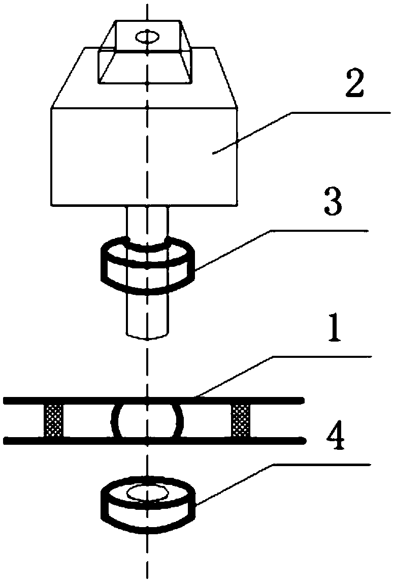
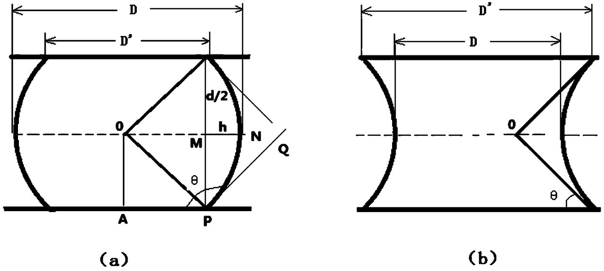
[0026] Determine the wettability of solid surfaces. Such as figure 1 , turn on the reflective light source 3, at this time the circle image of the contact surface between the liquid and the upper cover is the most obvious, and measure the diameter of the circle to be D'; turn on the transmission light source 4, at this time the microscopic system can clearly capture the circle image, The two diameters are measured as D and D' respectively, and the infiltration of the solid surface can be judged by comparing the sizes of D and D'. When D>D', the contact angle θ is greater than 90 degrees, that is, no wetting, such as image 3 (a); When D image 3 (b). The wetting angle is given by the formula Get it.

Embodiment 2

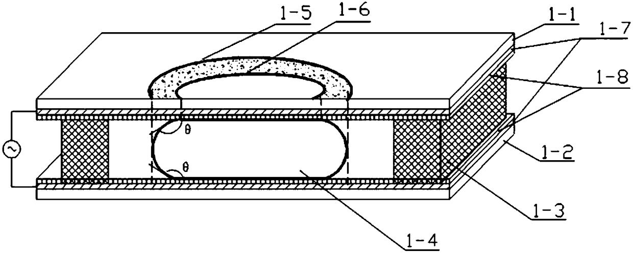
[0028] Measure the contact angles of two liquids with the same solid surface. Such as figure 2, replace the supporting columns 1-3 with sealing rings of thickness d, and pour transparent insulating oil that is immiscible with it around the conductive liquid droplet, and the oil can obviously increase the initial contact angle. In the same way, measure the parameters such as D, D', etc., and bring them into The contact angle can be found.


PUM


Abstract

A method for measuring the electrowetting effect of a micro-droplet comprises the following steps: placing a conductive micro-droplet in a droplet test box (1) formed by two flat electrodes having a spacing d and coating with insulation dielectric membranes, allowing the micro-droplet to be in full contact with the upper surface and the lower surface of the flat electrodes, and extruding to form a drum form; placing the droplet test box (1) on the objective table of a microscopic shooting system (2), arranging two light sources comprising an upper reflection light source (3) and a lower transmission light source (4) nearby the microscopic object lens of the system, wherein the reflection light source (3), the transmission light source (4) and the microscopic shooting system (2) are coaxially arranged; setting the diameter of the waist of the drum as D, and the diameter of the surface of the drum as D'; shooting a circular ring with the multiplying power of beta by the microscopic shooting system (2) in the irritation process of the transmission light source (4), acquiring the obtained image by a CCD camera arranged on a microscopic ocular lens, storing the acquired image in a computer by the CCD camera, and measuring to obtain the D and D' values; and representing the contact angle theta of the measured micro-droplet by using a function of the parameters D, D', d and beta, and calculating the contact angle theta and the change rule of the contact angle theta with voltage, that is the electrowetting effect. The reflection light source is mainly used to determine and measure the diameter D' of the surface of the drum.

Description

technical field [0001] The patent of the invention relates to a novel structure and working principle for measuring the variation of micro-droplet solid-liquid contact angle with voltage, that is, the electrowetting effect, and belongs to the technologies of photoelectric information integration devices, microfluidic optical analysis and self-adaptive optics. field. Background technique [0002] The electrowetting effect is a physical and chemical phenomenon, which changes the wettability of the droplet on the substrate by changing the voltage between the conductive droplet and the substrate, that is, changing the contact angle to cause the droplet to deform and displace. A micro-droplet is used as a lens, and the electrowetting method is used to change the shape of the micro-droplet to achieve the purpose of zooming. This zoom method effectively avoids the mechanical movement of the lens, can greatly reduce the volume of the lens, and does not have problems such as mechani...

Claims


Application Information

Patent Timeline
Patent Type & Authority Patents(China)
IPC IPC(8): G01N13/00
CPCG01N13/00
Inventor 陈陶方圆胡晨晨唐超梁忠诚
Owner NANJING UNIV OF POSTS & TELECOMM
Learn More