
Multi-type combined-hole-group numerical control processing method

A processing method and combined hole technology, applied in the direction of program control, computer control, general control system, etc., can solve the problems of high cost, high programming ability requirements, complicated work procedures, etc., and achieve low cost, strong portability, Simple working procedures

Inactive Publication Date: 2016-08-17
TIANJIN UNIV
View PDF5 Cites 14 Cited by
  • Summary
  • Abstract
  • Description
  • Claims
  • Application Information

AI Technical Summary

Problems solved by technology

In the NC machining process, the operator needs to set the program in the NC equipment according to the process. If manual programming is used, for the programming process of group holes and holes, it is necessary to calculate the coordinate value of each node, which not only requires a large amount of calculation, but also Low efficiency, error-prone, poor machining accuracy, and poor quality; if programming by calling subroutines, first write the subroutines, and then use the main program to call the subroutines for processing. It needs multiple calls to complete, which requires high programming ability of the operator; if automatic programming software such as CAM is used, the operator uses automatic programming software, such as UG, to complete the drawing of three-dimensional graphics, set the processing parts, and then create tools. The NC program can only be generated after setting the tool parameters and other steps. The working program is complicated, and the processing equipment needs to be equipped with automatic programming software such as CAM, which requires a relatively high configuration of the NC equipment and relatively high cost. It is suitable for composite processes or parts with complex shapes. Processing, not suitable for processing simple parts such as regular group holes

Method used


Image

  • Multi-type combined-hole-group numerical control processing method
  • Multi-type combined-hole-group numerical control processing method
  • Multi-type combined-hole-group numerical control processing method

Examples


Embodiment Construction

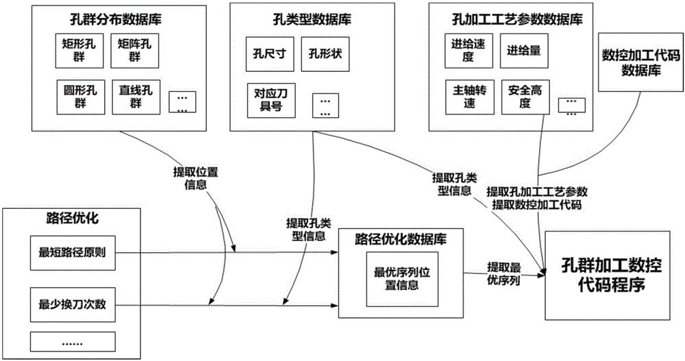
[0026] In order to further understand the invention content, characteristics and effects of the present invention, the following examples are given, and detailed descriptions are as follows in conjunction with the accompanying drawings:

[0027] see Figure 1 to Figure 6 , a multi-type combined hole group numerical control machining method, comprising the following steps:

[0028] Step 1: Establishing a hole group distribution database, a hole type database, a hole processing parameter database, and a NC machining code database; wherein, the hole type database and the hole processing parameter database are associated with the NC machining code database;

[0029] Step 2: Establish a human-computer interaction interface, input and call the data of the pore group distribution database, and generate a simulated pore group distribution schematic diagram;

[0030] Step 3: Establish a human-computer interaction interface, input and call the data of the hole type database, the hole p...


PUM


Abstract

The invention discloses a multi-type combined-hole-group numerical control processing method. The method comprises the following steps of step1, establishing a hole group distribution database, a hole type database, a hole processing technology parameter database and a numerical control processing code database; step2, establishing a man-machine interaction interface, logging and calling data of the hole group distribution database and generating a simulation hole group distribution sketch map; step3, establishing the man-machine interaction interface, logging and calling data of the hole type database, the hole processing technology parameter database and the numerical control processing code database; step4, setting a main shaft moving path optimization principle, optimizing calculation and automatically generating a main shaft moving optimization path; and step5, according to the main shaft moving optimization path, automatically generating a hole-group numerical control processing code program. In the invention, generation of single-type hole group and multi-type combined-hole-group processing codes can be realized; a work program is simple; an automatic programming function is possessed; cost is low and the method is suitable for parts used for processing regular hole groups.

Description

technical field [0001] The invention relates to a numerical control machining method, in particular to a numerical control machining method of multi-type combined hole groups. Background technique [0002] CNC machine tools often need to process some single holes, regular group holes, and multi-type regular group hole combinations, such as processing matrix-shaped group holes on steel plates, processing circular group holes on flanges or its rectangular holes and Hole groups formed by a combination of circular hole groups, etc. In the NC machining process, the operator needs to set the program in the NC equipment according to the process. If manual programming is used, for the programming process of group holes and holes, it is necessary to calculate the coordinate value of each node, which not only requires a large amount of calculation, but also Low efficiency, error-prone, poor machining accuracy, and poor quality; if programming by calling subroutines, first write the s...

Claims


Application Information

Patent Timeline
IPC IPC(8): G05B19/4097
CPCG05B19/4097G05B2219/36201
Inventor 王太勇张永宾董靖川丁彦玉于治强
Owner TIANJIN UNIV
Learn More