motor control unit

A control device and motor technology, applied in the direction of speed adjustment of multiple motors, control using feedback, etc., can solve problems such as vibration, inability to fully improve the control response of the servo controller, and difficulty in ensuring the synchronization accuracy of multiple motors

Active Publication Date: 2020-06-12
SANYO DENKI CO LTD
View PDF5 Cites 1 Cited by
  • Summary
  • Abstract
  • Description
  • Claims
  • Application Information

AI Technical Summary

Problems solved by technology

In addition, machines equipped with multiple motors and movable parts may vibrate due to driving
Therefore, the control response of the servo controller for each axis cannot be sufficiently improved.
Therefore, in the method of Japanese Patent Laid-Open Publication No. 2003-345442, when the control response of the servo controller cannot be sufficiently improved, it is difficult to ensure the synchronization accuracy among the plurality of motors.

Method used


Image

  • motor control unit
  • motor control unit
  • motor control unit

Examples


no. 1 approach

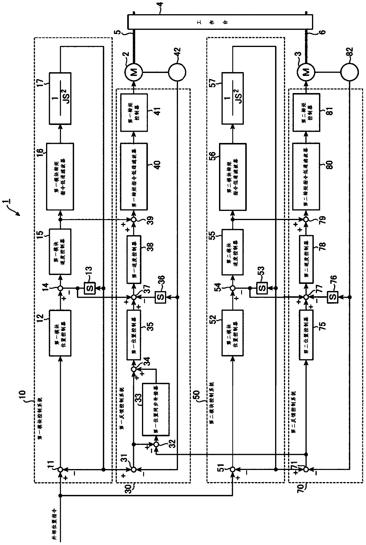
[0079] figure 1 It is a block diagram of the motor control device 1 according to the first embodiment of the present invention. exist figure 1 In the motor control device 1 shown, two motors, the first motor 2 and the second motor 3, drive one movable part in common. Accordingly, the motor control device 1 can specify the position of the movable portion at high speed and with high precision.

[0080] Such as figure 1 As shown, the motor control device 1 has: a first module control system 10 , a first feedback control system 30 , a second module control system 50 and a second feedback control system 70 .

[0081] An external position command indicating the control position of the table 4 as a movable part is input to the first module control system 10 . The first module control system 10 generates various first module instructions.

[0082] The first feedback control system 30 has a feedback loop including the first electric motor 2 . The first feedback control system 30 ...

no. 2 approach

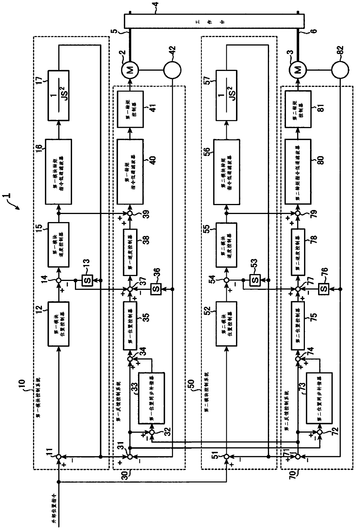
[0148] figure 2 It is a block diagram of a motor control device 1 according to a second embodiment of the present invention. figure 2 The motor control device 1 shown with figure 1 The difference between the shown device is that the second feedback control system 70 has a second synchronous position error obtainer 72 , a second position synchronous compensator 73 and a second synchronously compensated position error obtainer 74 .

[0149] The second synchronous position error obtainer 72, the second position synchronous compensator 73 and the second synchronous compensation position error obtainer 74 correspond to the first synchronous position error obtainer 32, the first position synchronous compensator 33 and the first synchronous compensation position Error acquirer 34.

[0150] Based on the second control position error acquired by the second control position error acquirer 71 and the first control position error acquired by the first control position error acquirer 3...

no. 3 approach

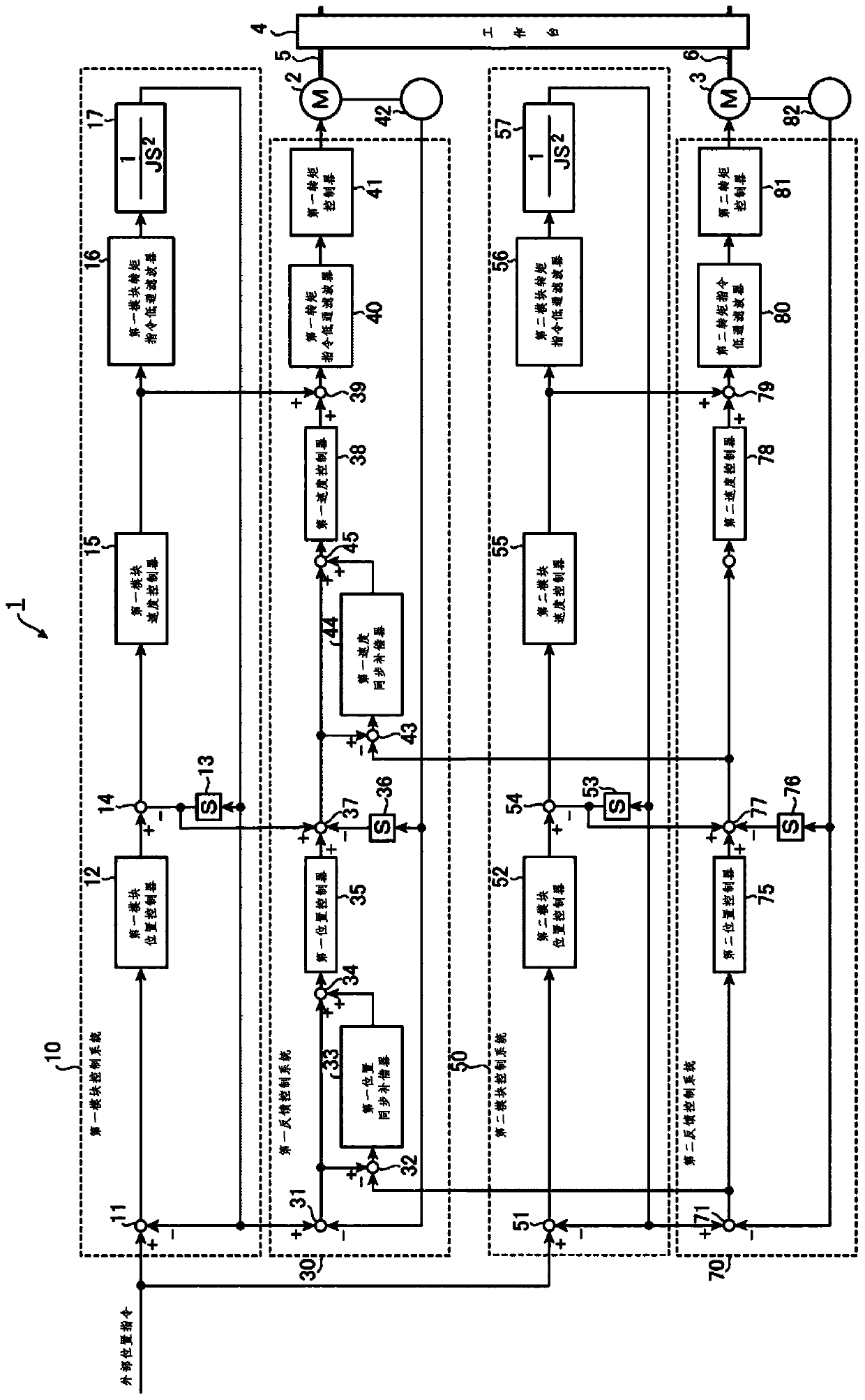
[0160] image 3 It is a block diagram of a motor control device 1 according to a third embodiment of the present invention. image 3 The motor control device 1 shown with figure 1 Compared with the shown device, the difference lies in that the first feedback control system 30 has: a first synchronous speed error obtainer 43 , a first speed synchronous compensator 44 and a first synchronous compensation speed error obtainer 45 .

[0161] Based on the first control speed error obtained by the first control speed error obtainer 37 and the second control speed error obtained by the second control speed error obtainer 77, the first synchronous speed error obtainer 43 obtains signals representing these control speed errors. The difference (synchronous speed error) is the first synchronous speed error. For example, the first synchronous speed error can be obtained by subtracting the other second control speed error from the first control speed error obtained by the first control sp...


PUM


Abstract

A motor control apparatus for cooperatively driving one movable portion with N pieces of motors, the motors being driven based on a common external position command, includes: a model control system that includes a movable portion model, the model control system being configured to generate a model command including a model position command based on the external position command; and N pieces of feedback control systems disposed corresponding to N pieces of the motors on a one-to-one basis, the feedback control systems being configured to perform a feedback control on the respective motors based on the model command. (N -1) pieces ofthe feedback control systems are configured to compensate a control error in controlling each of the motors with a difference between each of the control errors in the feedback control systems and a control error in the remaining one feedback control system.

Description

technical field [0001] The invention relates to a motor control device. Background technique [0002] In component mounting machines such as chip mounters, the number of components mounted per unit time can be increased by driving the movable portion with a motor at high speed to perform high-precision positioning. Thereby, the manufacturing cost related to component mounting work can be reduced. For example, in a large-scale chip mounter using a large table capable of simultaneously mounting a plurality of printed circuit boards, it is conceivable to drive one movable portion at high speed by a plurality of motors. [0003] For example, in the motor control device described in Japanese Patent Laid-Open Publication No. 2003-345442, one movable part is driven by two motors. The two motors are respectively controlled by a motor control module and a servo controller respectively arranged correspondingly to them. The servo controller actually controls the movement of the moto...

Claims


Application Information

Patent Timeline
Patent Type & Authority Patents(China)
IPC IPC(8): H02P5/52G05D3/12
CPCG05D3/12H02P5/52
Inventor 井出勇治北原通生平出敏雄
Owner SANYO DENKI CO LTD
Why Eureka
Try Eureka