Eureka AIR delivers breakthrough ideas for toughest innovation challenges, trusted by R&D personnel around the world.

Distribution line laying device

A technology for power distribution lines and supporting devices, which is applied in the direction of cable installation devices, cable installation, cable laying equipment, etc., and can solve the problem of inability to apply multiple sizes of reels, simultaneous laying of multiple cables, and manual laying of cables Low efficiency and other problems, to achieve the effect of improving the quality of power construction, improving the efficiency of power construction operations, and ensuring synchronization and consistency

Active Publication Date: 2021-01-05
国网山东省电力公司惠民县供电公司
View PDF6 Cites 0 Cited by
  • Summary
  • Abstract
  • Description
  • Claims
  • Application Information

AI Technical Summary

Problems solved by technology

[0003] In order to solve the current cable layout, the efficiency of manual cable layout is extremely low and the cables are easy to wear and tear, while the existing wiring equipment cannot be applied to reels of various sizes, has poor versatility, and cannot synchronize multiple cables Laying, it is easy to cause tensile damage to the cables, thus affecting the quality of electric power construction. The invention provides a distribution line laying device

Method used


Image

  • Distribution line laying device
  • Distribution line laying device
  • Distribution line laying device

Examples


Embodiment Construction

[0023]In order to make the objectives, features, and advantages of the present invention more obvious and understandable, the technical solutions of the present invention will be described clearly and completely in conjunction with the accompanying drawings in this specific embodiment. Obviously, the implementation described below The examples are only a part of the embodiments of the present invention, not all the embodiments. Based on the embodiments in this patent, all other embodiments obtained by those of ordinary skill in the art without creative work shall fall within the protection scope of this patent.

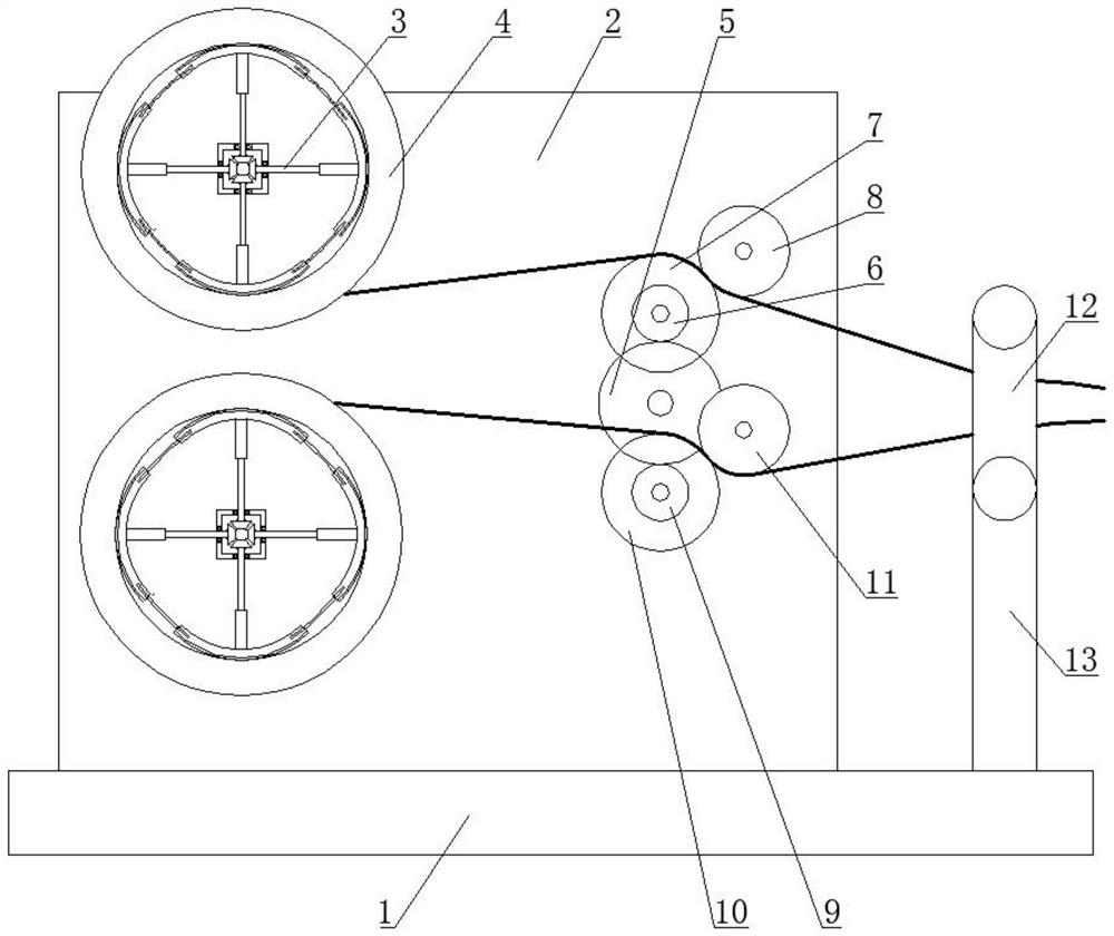
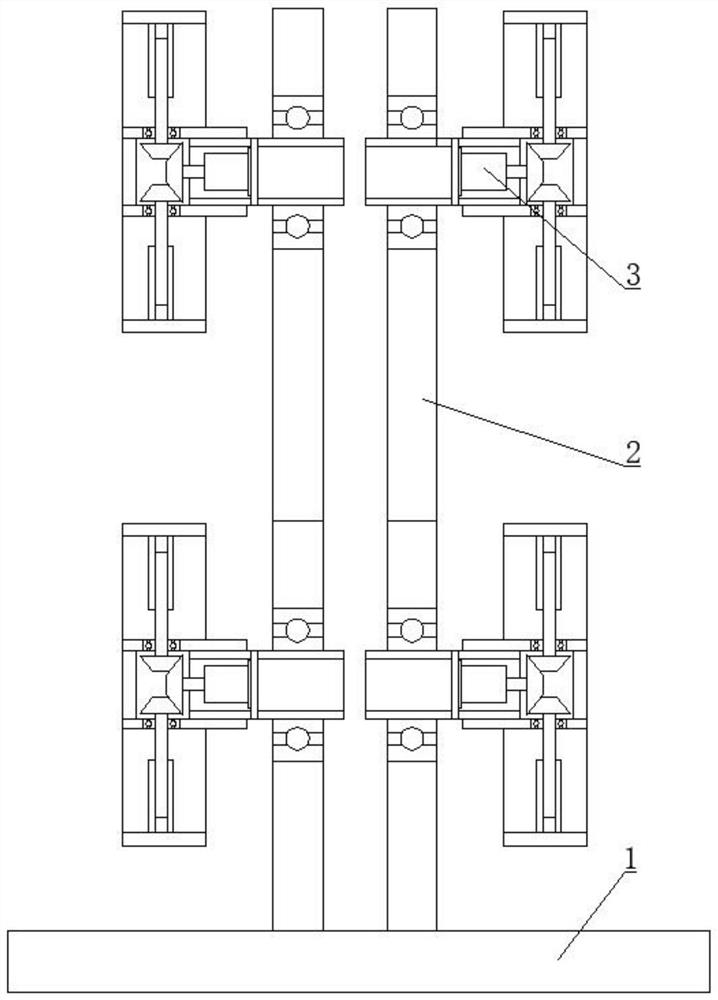
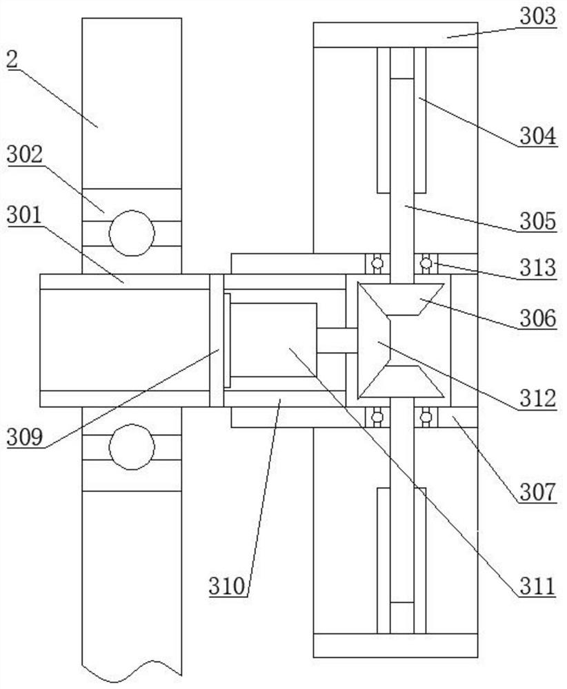
[0024]As shown in the figure, a power distribution line layout device includes a base 1 and a stand 2 that is vertically fixed and installed on the base 1. The stand 2 is rotatably installed with a main drive gear 5 and a first driven The gear 6, the first transmission wheel 7, the first driven pressure wheel 8, the second driven gear 9, the second transmission wheel 10, the s...


PUM


Abstract

The invention discloses a distribution line laying device, which belongs to the technical field of power construction, and comprises a base and a vertical frame. A main driving gear, a first driven gear, a first transmission wheel, a first driven pressing wheel, a second driven gear, a second transmission wheel, a second driven pressing wheel and two winding wheel supporting devices are rotationally mounted on the vertical frame; the main driving gear is driven by a motor; the first driven gear and the second driven gear are oppositely meshed with the two sides of the main driving gear, the first driven gear is coaxially and fixedly connected with the first transmission wheel, and the second driven gear is coaxially and fixedly connected with the second transmission wheel; the first drivenpressing wheel is arranged on the outer side of the first transmission wheel, and the second driven pressing wheel is arranged on the inner side of the second transmission wheel; the first driven pressing wheel and the first transmission wheel as well as the second driven pressing wheel and the second transmission wheel are used for pressing, rolling and transmitting different cables to finish wiring; and wiring operation can be synchronously carried out on various cables, the wiring efficiency is improved, tensile damage to the cables is avoided, and the power construction quality is improved.

Description

Technical field[0001]The invention belongs to the technical field of electric power construction, and specifically is a distribution line arrangement device.Background technique[0002]With the rapid growth of power demand in my country, the distribution and capacity of power sources have changed greatly, and the demand for mobile substations and box-type substations is increasing. Distribution cable routing is an important part of the installation of this type of substation, but due to the heavy weight of the coiled cable, manual cable routing is extremely inefficient and easy to wear. For cables of different models and specifications, the size of the reel is different, the existing wiring equipment is not applicable, the scope of application is small, and the versatility is poor; and when wiring cables, it is usually necessary to lay multiple cables at the same time. The existing wiring equipment cannot simultaneously lay multiple cables, and easily causes tensile damage to the cabl...

Claims


Application Information

Patent Timeline
IPC IPC(8): H02G1/00H02G1/06B65H54/44B65H54/547B65H57/06
CPCH02G1/00H02G1/06B65H54/44B65H54/547B65H57/06B65H2701/34
Inventor 李宁一王英波罗云张晓云尹梅琪王伟高启源
Owner 国网山东省电力公司惠民县供电公司
Why Eureka
Eureka Blog
Learn More