Segment crane and shield tunneling machine

A segment and crane technology, applied in mechanical equipment, load hanging elements, wellbore lining, etc., can solve the problems affecting the working efficiency of the shield machine, downtime for maintenance, etc.

Pending Publication Date: 2021-08-24
CHINA RAILWAY ENGINEERING EQUIPMENT GROUP CO LTD
View PDF15 Cites 1 Cited by
  • Summary
  • Abstract
  • Description
  • Claims
  • Application Information

AI Technical Summary

Problems solved by technology

[0004] The purpose of the present invention is to provide a segment crane to solve the technical problem that the single synchronous action control mode in the prior art cannot deal with the large stroke difference between the two hydraulic cylinders in the segment crane
At the same time, the present invention also provides a shield machine using the above-mentioned segment crane to solve the problem that the single synchronous action control mode of the segment crane in the prior art needs to be shut down for maintenance, which easily affects the shield machine. Technical issues of work efficiency

Method used


Image

  • Segment crane and shield tunneling machine
  • Segment crane and shield tunneling machine
  • Segment crane and shield tunneling machine

Examples


specific Embodiment 1

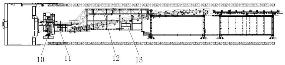
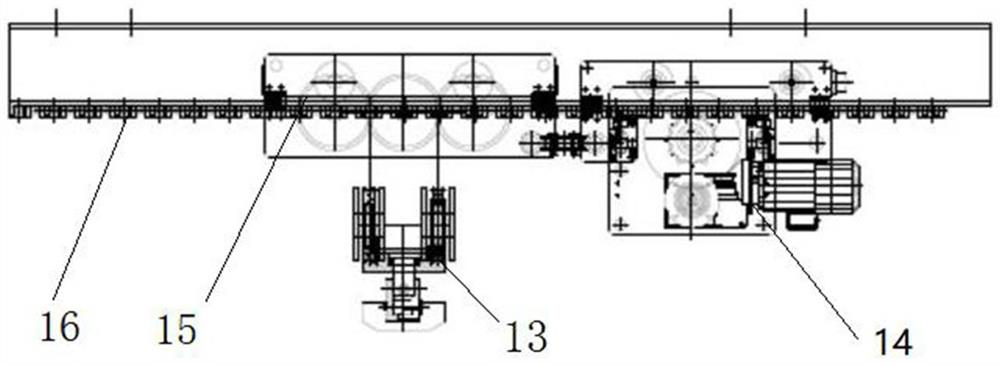
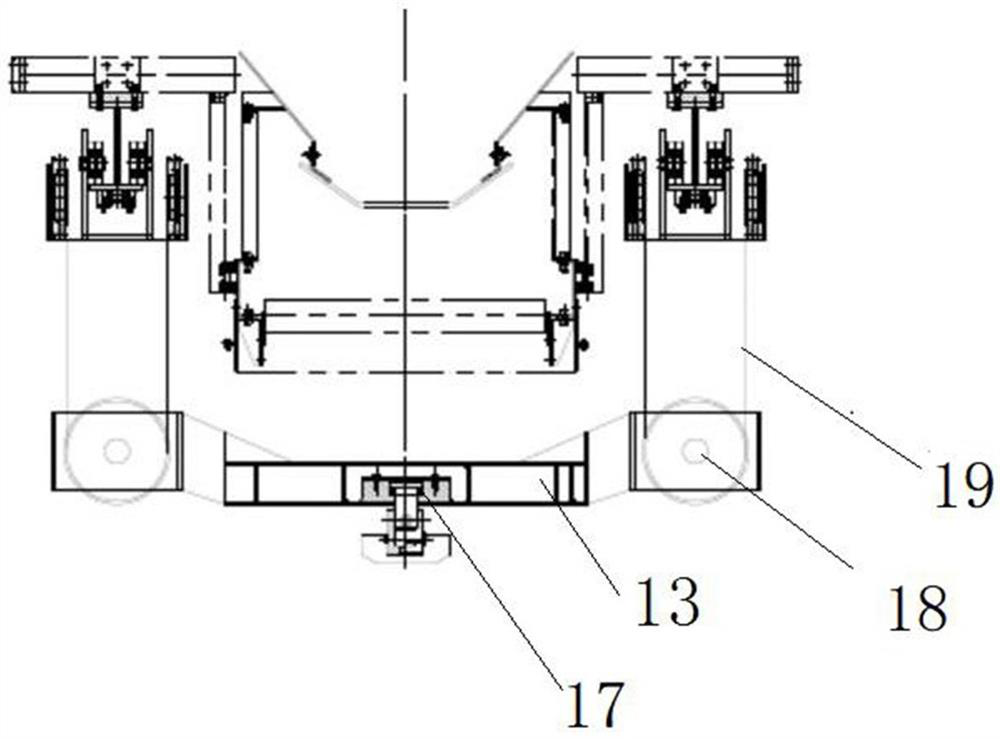
[0071] Such as Figure 1 to Figure 4 As shown, the shield machine in this embodiment includes a main beam 11, a main drive is arranged at the front of the main beam 11, and a shield body is arranged outside the main drive, and the main drive is used to drive the cutter head to rotate. A segment laying machine 10 is installed on the rear side, and the segment laying machine 10 is used to lay the segment in the tunnel to form a segment ring, and a segment crane is slidably installed on the equipment bridge 12 at the rear side of the main girder 11 The machine 13 is used for hoisting and transporting the segments on the marshalling train to the segment laying machine 10.

[0072] The equipment bridge 12 is provided with a track beam 16, and the track beam 16 is reciprocatingly equipped with a segment crane 13 along the front and rear direction. Two hydraulic cylinders 15 extending horizontally are arranged on the top, and the output ends of the two hydraulic cylinders 15 drive t...

specific Embodiment 2

[0093] The main difference between it and Embodiment 1 is that in Embodiment 1, the rodless cavity oil circuit and the rod cavity oil circuit of each hydraulic circuit have two branch oil circuits respectively, which can realize height and low speed control. In this embodiment, the rodless cavity oil circuit and the rod cavity oil circuit of each hydraulic circuit respectively have more than three branch oil circuits, correspondingly, more than three reversing valves can be configured to realize high, medium and low speed control.

[0094] Of course, in other embodiments, each hydraulic circuit can also only be provided with a reversing valve. At this time, no branch oil circuit is provided. At this time, although the control of different speeds cannot be realized, the synchronization of the two hydraulic cylinders can still be controlled. Actions and single hydraulic cylinder actions still have multiple control modes.

specific Embodiment 3

[0096] The main difference between it and Embodiment 1 lies in that in Embodiment 1, a synchronous speed regulating valve is set on each branch oil circuit with a rod cavity to realize the synchronous action of the two hydraulic cylinders. In this embodiment, a synchronous speed regulating valve can also be set on the branch oil circuit of the rod cavity, or a synchronous speed regulating valve can be respectively set on the branch oil circuit of the rod cavity and the branch oil circuit of the rodless cavity, so as to realize the synchronization of the two hydraulic cylinders. action.


PUM


Abstract

The invention relates to a segment crane and a shield tunneling machine. The segment crane comprises two hydraulic oil cylinders and a hydraulic control system, wherein the hydraulic control system comprises two hydraulic loops; each hydraulic loop is provided with a rodless cavity oil way, a rod cavity oil way and a reversing valve; each reversing valve communicates the rodless cavity oil way and the rod cavity oil way of the corresponding hydraulic loop with an oil supply oil way and an oil return oil way so as to control the hydraulic oil cylinder to stretch and retract through the reversing valve; the reversing valve is provided with a locking middle position and used for controlling and locking the rod cavity oil way and the rodless cavity oil way of the corresponding hydraulic loop so as to lock the hydraulic oil cylinder; and a synchronous speed control valve is arranged on the rodless cavity oil way and / or the rod cavity oil way on the two hydraulic loops so as to realize synchronous action of the two hydraulic oil cylinders. Different control modes are selected according to actual working requirements, the two hydraulic oil cylinders can be controlled to act synchronously, the single hydraulic oil cylinder can also be controlled to act, and the actual working requirements are met.

Description

technical field [0001] The invention relates to a segment crane and a shield machine. Background technique [0002] In the shield machine, a segment paving machine is installed on the trolley at the front to lay the segment into a segment ring, wherein the segment is hoisted by the segment crane from the marshalling train to the transport trolley, and then The segment is transferred to the segment laying machine by the transport trolley, such as the shield machine disclosed in the Chinese invention patent application with the application publication number CN111622764A. In fact, the more commonly used segment cranes at present use a hydraulic cylinder segment crane similar to the authorized announcement number CN209193423U to realize the lifting of segments, that is, the hydraulic cylinders are arranged horizontally. The steel wire rope drives the segments up and down. [0003] For the shield machine, the stability and safety of the segment crane directly affect the effici...

Claims


Application Information

Patent Timeline
Patent Type & Authority Applications(China)
IPC IPC(8): F15B11/22F15B11/04F15B20/00B66C13/20E21D11/40E21D9/06
CPCF15B11/22F15B11/04F15B11/003F15B20/004B66C13/20E21D11/40E21D9/0607F15B2211/40F15B2211/72F15B2211/75F15B2211/782
Inventor 郭攀登李太运朱雷张杰蔡留金马志勇罗恒星赵康峰李东辉詹晨菲
Owner CHINA RAILWAY ENGINEERING EQUIPMENT GROUP CO LTD
Why Eureka
Try Eureka