Water-drop-shaped magnetic rod

A drop-shaped, magnetic rod technology, applied in the direction of magnetic separation, solid separation, chemical instruments and methods, etc., can solve the problem that the cylindrical magnetic rod cannot effectively control the material flow trajectory, cannot effectively control the material flow trajectory, and the cylindrical magnetic rod Small flow area and other problems, achieve good iron removal effect, improve iron removal effect, and improve iron removal effect

Inactive Publication Date: 2016-08-24
南通麦克斯威尔机电设备有限公司
View PDF7 Cites 4 Cited by
  • Summary
  • Abstract
  • Description
  • Claims
  • Application Information

AI Technical Summary

Problems solved by technology

Cylindrical magnetic rods have small front flow area and poor handling effect
[0008] 3. Cannot effectively control the material flow trajectory, affecting the iron removal effect
[0009] The magnetic rods in the iron remover are generally arranged in double or multiple layers, the upper and lower layers are staggered, and the upstream surface of the magnetic rods guides the material flow, so that the material flow can be more efficient after being guided by the upper layer of magnetic rods. Fully contact the upstream surface of the next layer of magnetic rods to improve the iron removal effect. Cylindrical magnetic rods cannot effectively control the material flow trajectory, and the treatment effect is not good

Method used


Image

  • Water-drop-shaped magnetic rod
  • Water-drop-shaped magnetic rod
  • Water-drop-shaped magnetic rod

Examples


Embodiment 1

[0031] refer to Figure 6 Shown, a kind of water-drop type magnet bar comprises water-drop type monolithic magnetic core, and described magnetic core comprises magnetic material piece 2 and magnetic pole piece 1, and described magnetic material piece and described magnetic pole piece pass core bar 3 and nut 4 ( or other means) fixed as a whole.

Embodiment 2

[0033] refer to Figure 7 As shown, a droplet-shaped magnetic bar includes a droplet-shaped integral magnetic core, and the magnetic core includes a magnetic material block 2 and a magnetic pole piece 1, and the magnetic material block 2 and the magnetic pole piece 1 pass through a core rod 3 and a nut 4 (or other methods) fixed together, the outside of the magnetic core is provided with a stainless steel tube 5 with a drop-shaped cross-section, the stainless steel tube 5 is a sleeve, and one end of the stainless steel tube 5 is welded or bonded with a drop-shaped end plug , the other end is open, during normal operation, the magnetic core is plugged in the casing, the outside of the casing is in contact with the material, the magnetic pollutants in the material are adsorbed outside the casing, and the magnetic core is pulled out of the casing when it is necessary to unload the iron , the magnetic pollutants adsorbed on the outside of the bushing will fall off naturally due to...

Embodiment 3

[0035] refer to Figure 8 As shown, a droplet-shaped magnetic bar includes a droplet-shaped integral magnetic core, and the magnetic core includes a magnetic material block 2 and a magnetic pole piece 1, and the magnetic material block 2 and the magnetic pole piece 1 pass through a core rod 3 and a nut 4 (or in other ways) fixed together, the outside of the magnetic core is wrapped with a stainless steel tube 5 with a drop-shaped cross-section, and the two ends of the stainless steel tube 5 are formed by welding or adhesively sealing with a water-drop-shaped end plug.

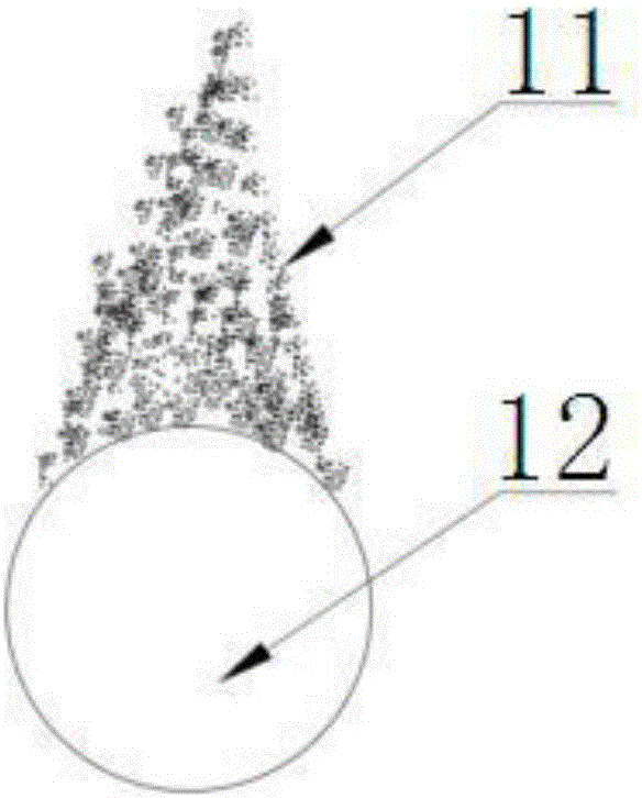
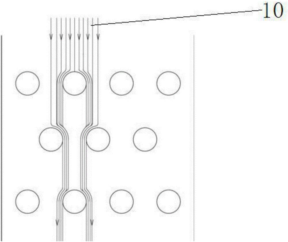
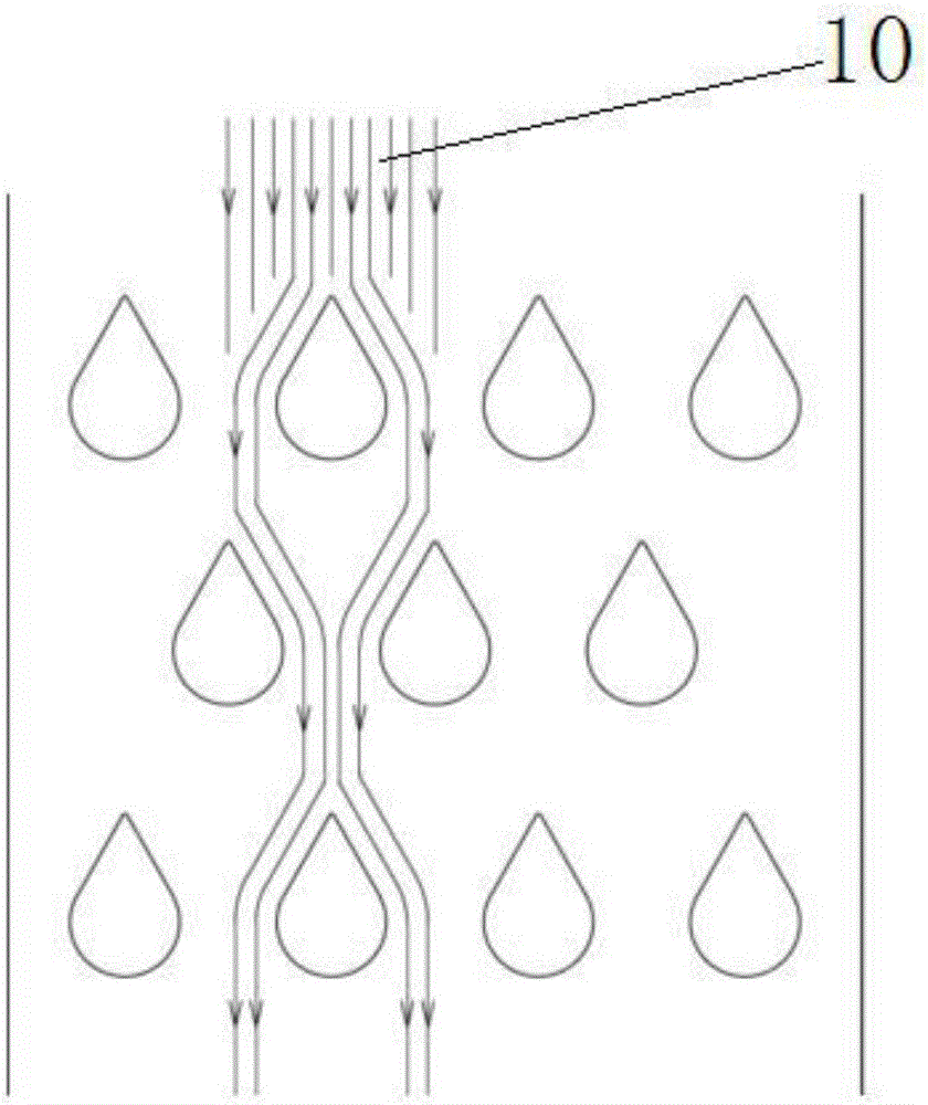
[0036] refer to figure 1 , figure 2 , image 3 , Figure 4 and Figure 5 As shown, the present invention changes the traditional circular magnetic bar into a water drop-shaped magnetic bar. When the material 11 falls from above, the material 11 fully contacts the upstream surface 6 of the water-drop-shaped magnetic bar, and the upstream surface 6 of the water-drop-shaped magnetic bar is larger than On the...


PUM


Abstract

The invention discloses a water-drop-shaped magnetic rod. The section of the magnetic rod is water-drop-shaped; the water-drop-shaped magnetic rod is changed on the basis of a traditional cylindrical magnetic rod; iron removal effect is improved; the water-drop-shaped magnetic rod has the advantages of preventing material accumulation, increasing the flow contact surface and effectively controlling the material flowing track.

Description

technical field [0001] The invention relates to the technical field of magnetic materials, in particular to a drop-shaped magnetic bar. Background technique [0002] The magnetic rod is the core component of the permanent magnet grid type iron remover. The current permanent magnet grid type iron remover adopts a magnetic rod with a circular cross section to form a grid. [0003] However, there are the following problems and disadvantages in the round magnetic rod: [0004] 1. Material accumulation seriously affects the iron removal effect [0005] When the powder material with less than ideal fluidity passes through the grid, the upper surface of the cylindrical magnetic bar (upstream surface) has material accumulation, forming a mountain peak. Magnetism, the elemental iron in the subsequent passing materials will be adsorbed on the outer surface of the mountain peak, and in the subsequent material scouring, the mountain peak will collapse to the processed materials, causi...

Claims


Application Information

Patent Timeline
Patent Type & Authority Applications(China)
IPC IPC(8): B03C1/02
CPCB03C1/02
Inventor 顾明明
Owner 南通麦克斯威尔机电设备有限公司
Why Eureka
Try Eureka