Multistage-separation efficient centrifugal machine

A multi-stage separation and centrifuge technology, applied in the field of centrifuges, can solve the problems of material loss, scraped material splashing, poor scraper scraping effect, etc., and achieve the effect of reasonable structure design.

Active Publication Date: 2016-08-24
优承生物科技(烟台)有限公司
View PDF8 Cites 3 Cited by
  • Summary
  • Abstract
  • Description
  • Claims
  • Application Information

AI Technical Summary

Problems solved by technology

When the scraper is used to scrape the material, when the drum is rotating, the fixed scraper scr

Method used


Image

  • Multistage-separation efficient centrifugal machine

Examples


Embodiment Construction

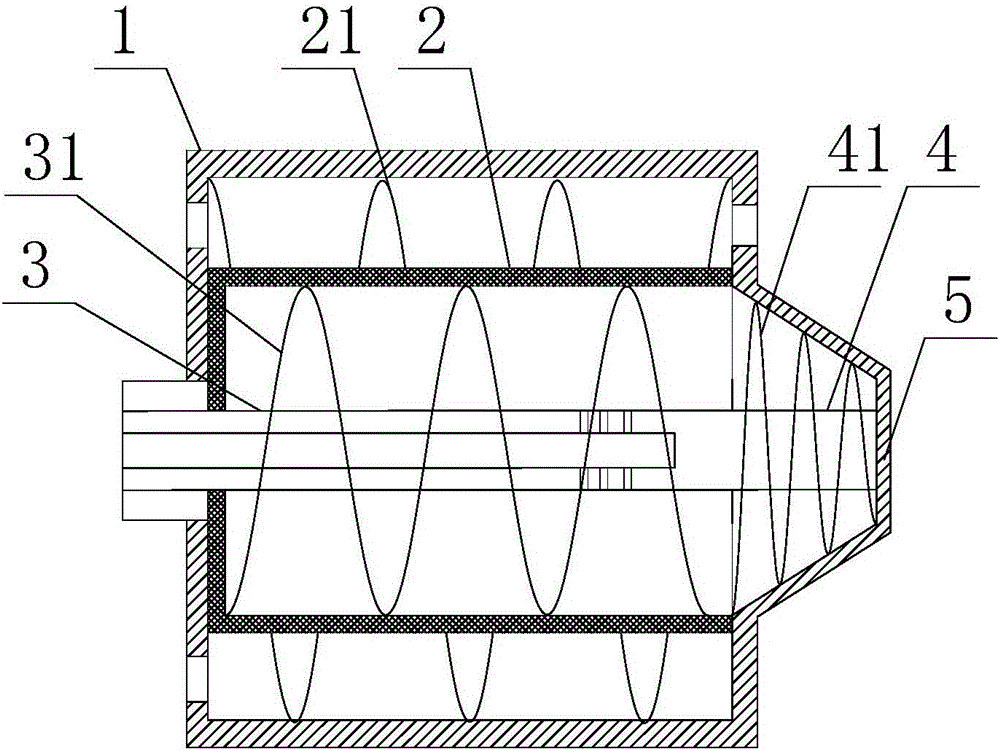
[0016] Such as figure 1 as shown, figure 1 It is a structural schematic diagram of a multi-stage separation high-efficiency centrifuge proposed by the present invention.

[0017] refer to figure 1 , a high-efficiency centrifuge with multi-stage separation proposed by the present invention, comprising: a drum 1, a drum 2, a first screw mechanism 3, a second screw mechanism 4, a storage cover 5, a first drive mechanism, a second drive mechanism, the third driving mechanism;

[0018] The drum 1 is arranged horizontally, the first end of the drum 1 is provided with a feed port and a liquid outlet and the second end is provided with a first discharge port and a second discharge port, and the inside of the drum 1 is provided with a an accommodating chamber extending from the second end;

[0019] The rotating drum 2 is arranged horizontally in the containing chamber and coaxially arranged with the rotating drum 1, and the rotating drum 2 divides the containing chamber into a firs...


PUM


Abstract

The invention discloses a multistage-separation efficient centrifugal machine. A rotary drum is horizontally arranged in a roller. A first spiral blade is arranged on the periphery of the rotary drum and is in clearance fit with the inner wall of the roller. A spiral mechanism is arranged in the rotary drum and is coaxial with the rotary drum. A second spiral blade is arranged on the periphery of the spiral mechanism and is in clearance fit with the inner wall of the rotary drum. A feeding cavity is formed in the spiral mechanism. A material distributing hole is formed in the side wall of the feeding cavity. By means of the above multistage-separation efficient centrifugal machine optimally designed, the structural design is reasonable, slurry to be separated enters the rotary drum through a feeding cavity, the solid material is intercepted in the rotary drum, the liquid material enters a second separation cavity through a mesh of the rotary drum and rotates at a high speed along with the roller, small solid particles in the liquid material are attached to the inner wall of the roller, and therefore multistage separation of the solid-phase material different in particle size from the liquid phase is achieved.

Description

technical field [0001] The invention relates to the technical field of centrifuges, in particular to a multi-stage separation high-efficiency centrifuge. Background technique [0002] A centrifuge is a machine that uses the inertial centrifugal force generated by the rotation of the drum to separate or concentrate suspensions, emulsions, and other heterogeneous materials. The scraper discharge centrifuge is mainly composed of a high-speed rotating drum, a transmission device, and a scraper discharging device. The working principle is: when the suspension to be separated enters the centrifuge drum, the high-speed rotating drum generates a powerful Centrifugal force deposits the solid phase particles on the inner wall of the drum, and is trapped in the drum by the filter screen, the liquid phase is filtered out through the filter screen, and the solid phase trapped in the inner wall of the drum is scraped out by the scraper and discharged out of the drum. When the scraper is ...

Claims


Application Information

Patent Timeline
IPC IPC(8): B04B1/20B04B11/02
CPCB04B1/20B04B11/02
Inventor 崔李黄艳
Owner 优承生物科技(烟台)有限公司
Why Eureka
Try Eureka