Clamping jaw assembly for automatic laminating machine of antenna terminal
What is Al technical title?
Al technical title is built by PatSnap Al team. It summarizes the technical point description of the patent document.
An antenna terminal and press machine technology, applied in metal processing, metal processing equipment, manufacturing tools, etc., can solve the problems affecting the service life and performance of products, affecting production efficiency and product quality, and high technical requirements for workers' assembly. The effect of good clamping effect, less workpiece wear and long service life
Active Publication Date: 2016-08-24
贵阳渝冠技术服务中心
View PDF6 Cites 12 Cited by
Summary
Abstract
Description
Claims
Application Information
AI Technical Summary
This helps you quickly interpret patents by identifying the three key elements:
Problems solved by technology
Method used
Benefits of technology
Problems solved by technology
[0002] At present, the antennas in computers, mobile phones, and tablet computers are composed of wire ends and terminals. However, the jaw components of the existing antenna terminal automatic pressing machine have complex structure, low efficiency, low precision, unstable operation, and large batches. The assembly line production is done manually by workers, and the production process has relatively high requirements on the assembly technology of workers. Once there is a flow and replacement of workers, it will affect the production efficiency and product quality, and directly affect the service life and performance of the product. In view of this , it is necessary to improve the jaw assembly of the existing automatic antenna terminal pressing machine
Method used
Image
Click on the blue label to locate the original text in one second.
Reading with bidirectional positioning of images and text.
Examples
Embodiment Construction
[0009] The preferred embodiments of the present invention will be described in detail below in conjunction with the accompanying drawings, so that the advantages and features of the present invention can be more easily understood by those skilled in the art, so as to define the protection scope of the present invention more clearly.
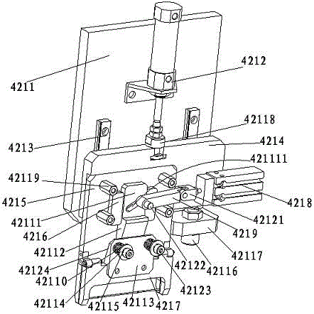
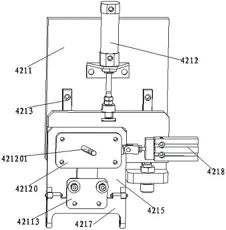
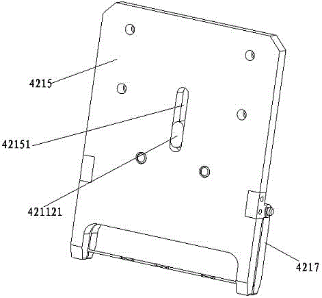
[0010] see Figure 1 to Figure 3 Embodiments of the invention include:
[0011] A clamping jaw assembly of an automatic antenna terminal pressing machine, the clamping jaw assembly of the automatic antenna terminal pressing machine includes a material picking assembly mounting plate 4211, a clamping jaw pushing cylinder 4212, a linear guide rail 4213, a slide plate 4214, a clamping jaw plate 4215, Limiting plate 4216, gripper 4217, jaw separation cylinder 4218, linear connecting rod 4219, spring 42110, lifting block 42111, wedge block 42112, gripper separation block 42113, fixing ring 42114, bolt washer 42115, adjustment positioning shaft 42116 ...
PUM
Abstract
The invention discloses a clamping jaw assembly for an automatic laminating machine of an antenna terminal. The clamping jaw assembly for the automatic laminating machine of the antenna terminal comprises a reclaiming assembly mounting plate, a clamping jaw push air cylinder, a linear guide rail, a sliding plate, a clamping jaw plate, a limiting plate, a gripping hand, a clamping jaw separating air cylinder, a linear connecting rod, a spring, a lifting block, a wedge block, a gripping hand separating block, a fixed ring, a bolt gasket, an adjusting locating shaft, an adjusting locating shaft fixing plate, a round floating contact, a fixed support post, a reclaiming guide plate, a double-lug connector, a guide cylinder, a hexagon socket screw and a tilt block, wherein the reclaiming assembly mounting plate is fixed on the lower plane of a manipulator connecting plate through a reinforcing rib; the gripping hand push air cylinder is longitudinally fixed on the side surface of the reclaiming assembly mounting plate; and the round floating contact is arranged at the end of a piston rod of the clamping jaw push air cylinder. According to the clamping jaw assembly, the operation is convenient; the abrasion on a workpiece is small; the service lifetime is long; the production efficiency is improved; and the production cost is reduced.
Description
technical field [0001] The invention relates to the field of mechanical automation, in particular to a jaw assembly of an automatic pressing machine for antenna terminals. Background technique [0002] At present, the antennas in computers, mobile phones, and tablet computers are composed of wire ends and terminals. However, the jaw components of the existing antenna terminal automatic pressing machine have complex structure, low efficiency, low precision, unstable operation, and large batches. The assembly line production is done manually by workers, and the production process has relatively high requirements on the assembly technology of workers. Once there is a flow and replacement of workers, it will affect the production efficiency and product quality, and directly affect the service life and performance of the product. In view of this , it is necessary to improve the jaw assembly of the existing automatic pressing machine for antenna terminals. Contents of the invent...
Claims
Application Information
Patent Timeline
Application Date:The date an application was filed.
Publication Date:The date a patent or application was officially published.
First Publication Date:The earliest publication date of a patent with the same application number.
Issue Date:Publication date of the patent grant document.
PCT Entry Date:The Entry date of PCT National Phase.
Estimated Expiry Date:The statutory expiry date of a patent right according to the Patent Law, and it is the longest term of protection that the patent right can achieve without the termination of the patent right due to other reasons(Term extension factor has been taken into account ).
Invalid Date:Actual expiry date is based on effective date or publication date of legal transaction data of invalid patent.