Cutting mechanism for injection molding material head

A technology of injection molded parts and material heads, which is applied in the field of injection molded parts material head cutting mechanism, can solve the problems of unsuitable injection molded parts removal, unstable clamping of injection molded parts, uneven material head removal, etc., and achieve good cutting quality and simple structure , a wide range of effects

Inactive Publication Date: 2016-08-24
SUZHOU WANSHENG PLASTIC TECH CO LTD
View PDF7 Cites 3 Cited by
  • Summary
  • Abstract
  • Description
  • Claims
  • Application Information

AI Technical Summary

Problems solved by technology

However, the existing cutting device has the following defects: (1) The clamping of the injection molded parts is not stable, resulting in uneven cutting of the material head, and may damage the injection molded parts; (2) It is not suitable for cutting injection molded parts of different sizes, and the scope of application is narrow

Method used


Image

  • Cutting mechanism for injection molding material head
  • Cutting mechanism for injection molding material head

Examples


Embodiment Construction

[0014] The present invention will now be further described in detail in conjunction with the accompanying drawings and embodiments. These drawings are all simplified schematic diagrams, only illustrating the basic structure of the present invention in a schematic manner, so it only shows the composition related to the present invention.

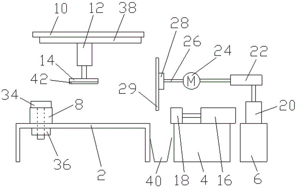
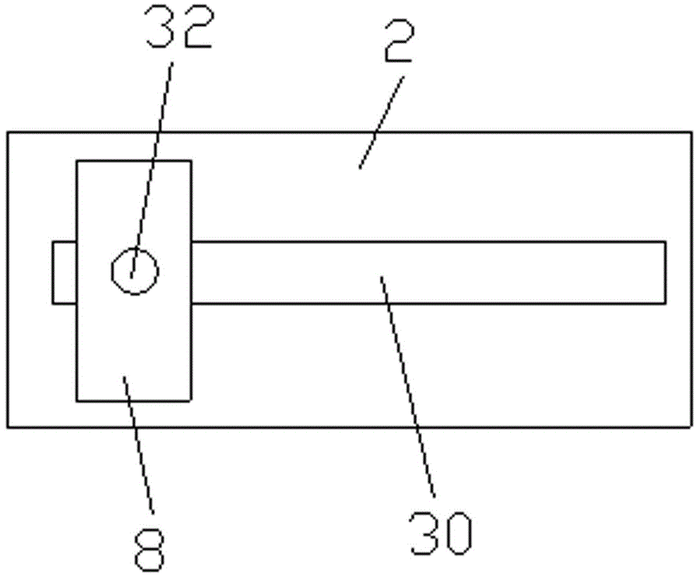
[0015] like figure 1 As shown, an injection molded part head cutting mechanism includes a first base 2, a second base 4 and a third base 6 arranged horizontally and sequentially. The first base 2 is provided with a first baffle 8, and the first base 2 A crossbeam 10 is arranged above, and a first cylinder 12 is installed on the crossbeam 10, the first cylinder 12 is vertically arranged, the first cylinder 12 is connected with a pressure plate 14, the second base 4 is fixed with a second cylinder 16, and the second cylinder 16 is horizontal Set, the second cylinder 16 is fixed with the second baffle plate 18, the third base 6 is provided with ...


PUM


Abstract

The invention relates to a cutting mechanism for an injection molding material head. The cutting mechanism comprises a first base, a second base and a third base which are horizontally arranged in sequence. The first base is provided with a first baffle, and a cross beam is arranged above the first base. The cross beam is provided with a first cylinder, and the first cylinder is connected with a pressing plate. The second base is fixedly connected with a second cylinder, and the second cylinder is fixedly connected with a second baffle. The third base is provided with a cutting assembly. The cutting assembly comprises a third cylinder, a fourth cylinder fixedly connected with the third cylinder, a motor fixedly connected with the fourth cylinder, a cutter rest fixedly connected with an output shaft of the motor, and a cutter fixed to the cutter rest. The cutting mechanism for the injection molding material head is simple in structure and convenient to use. Through the coordination of the first baffle, the second baffle and the pressing plate, injection moldings can be clamped, and accordingly the material head can be cut off quickly through the cutter. Working efficiency is high and cutting quality is good. Meanwhile, the position of the first baffle and the position of the pressing plate can be adjusted, the injection moldings of different sizes can be clamped conveniently, and therefore the application range is wide, and production cost is reduced.

Description

technical field [0001] The invention relates to the technical field of injection molded parts processing, in particular to a material head cutting mechanism for injection molded parts. Background technique [0002] Injection molded parts refer to the collective name of various injection molded products produced by injection molding machines, including various packaging, parts, etc., which are mainly made of polyethylene or polypropylene and other materials with the addition of various organic solvents. During the processing of injection molded parts, there are usually material heads generated by the injection port, and these excess material heads need to be cut off. However, the existing cutting device has the following defects: (1) The clamping of the injection molded part is not stable, resulting in uneven cutting of the material head, and may damage the injection molded part; (2) It is not suitable for cutting injection molded parts of different sizes, and the applicable ...

Claims


Application Information

Patent Timeline
IPC IPC(8): B29C45/38
CPCB29C45/382
Inventor 赵正华
Owner SUZHOU WANSHENG PLASTIC TECH CO LTD
Why Eureka
Try Eureka