
Cooling tank

A technology for cooling water tanks and water tanks, applied in the field of cooling water tanks, which can solve problems such as unfavorable drying of reinforced composite material strips, difficult adjustment of walking distance, waste of clean water resources, etc., and achieve the effect of saving clean cooling water sources

Active Publication Date: 2018-05-18
NANJING GIANT MACHINERY
View PDF4 Cites 2 Cited by
  • Summary
  • Abstract
  • Description
  • Claims
  • Application Information

AI Technical Summary

Problems solved by technology

[0003] At present, the traditional cooling water tank is used to cool and shape the strips of reinforced composite materials, which will cause eccentricity and unevenness of the polymer coating layer. The water temperature and water level of the cooling water tank are not easy to control, and the strips of reinforced composite materials are immersed in water. The walking distance is not easy to adjust, and it is not conducive to the drying of the surface of the strip of reinforced composite material after exiting the water
In order to meet the technological requirements of maintaining the cooling water temperature and water level in the traditional cooling water tank, an external direct connection to the clean cooling water source is used, and the clean cooling water is filled and self-overflowing in the water tank, resulting in a waste of clean water resources
Although the traditional cooling water tank has a simple structure and low manufacturing cost, the use cost is too high and it is not easy to operate

Method used

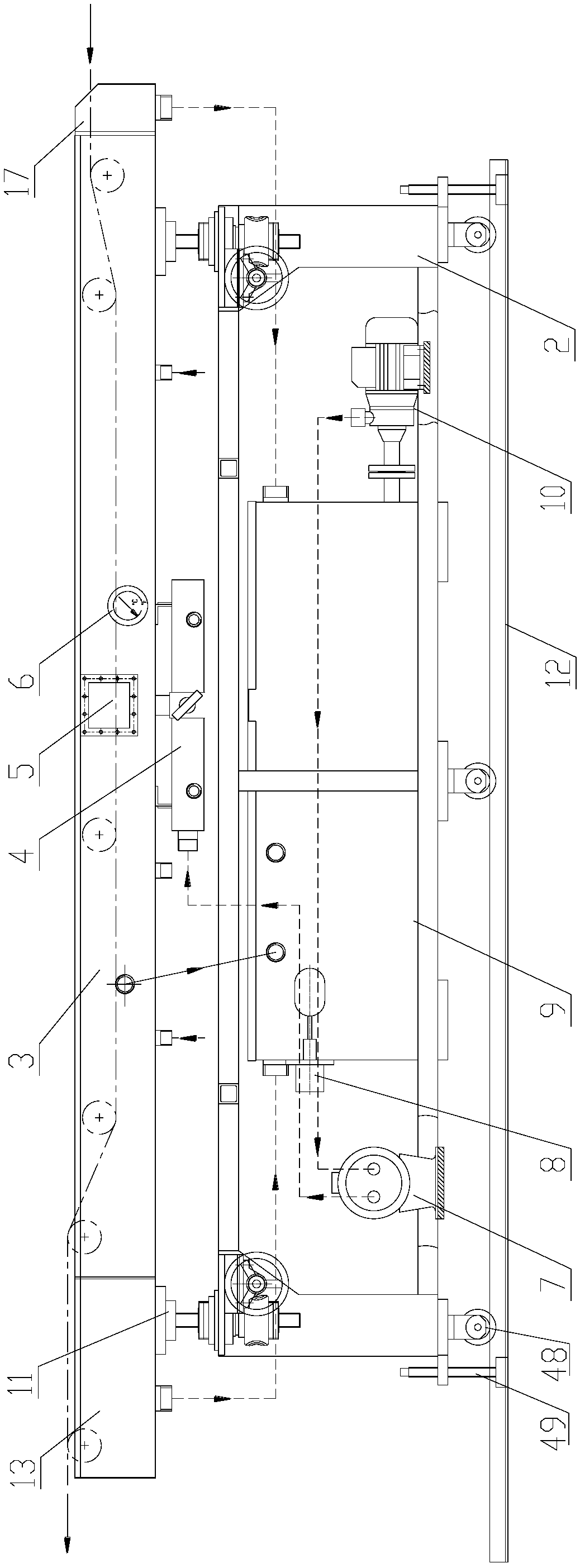

Image

  • Cooling tank
  • Cooling tank
  • Cooling tank

Examples


Embodiment Construction

[0038] The present invention will be further explained below in conjunction with the accompanying drawings.

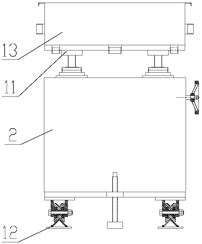
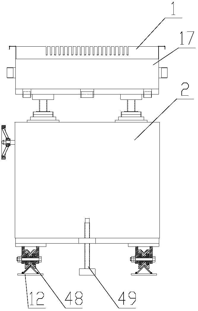
[0039] Such as Figures 1 to 3 As shown, a cooling water tank of the present invention includes an underframe composition 2 , a water tank composition 3 and a guide rail composition 12 . The lower part of the chassis composition 2 is provided with a pulley 48, and the pulley 48 can slide on the guide rail composition 12, so that the cooling water tank can move back and forth as a whole. There are bolt installation positioning holes matched with the adjusting bolt 49, and the base frame composition 2 and the guide rail composition 12 can be relatively fixed by the adjusting bolt 49, so as to stabilize the working position of the cooling water tank.

[0040] Such as figure 1 , 5 As shown in and 6, the top of the chassis composition 2 is provided with a height-adjustable up and down displacement device 11. The up and down displacement device 11 includes a worm spindle 2...


PUM


Abstract

The invention discloses a cooling water tank, which comprises a chassis component, wherein the lower part of the chassis component is provided pulleys; the upper part of the chassis component is provided with height-adjustable up-down displacing devices; a water tank component, a water receiving case and an air-drying water receiving case are connected into a whole, and are mounted at the upper parts of the up-down displacing devices; the water tank component is provided with sliver roller components, water supply pipes and side water discharge components; the water receiving case and the air-drying water receiving case are both provided with water discharge interfaces; the air-drying water receiving case is also provided with a sliver roller component; a water storage box component is arranged inside the chassis component; a water inlet interface of the water storage box is connected with a water discharge interface; a water outlet interface of the water storage box component is connected with a water inlet interface of a water-cooled heat exchanger through a water pump; and a water outlet interface of the water-cooled heat exchanger is connected with the water supply pipes through a water system component. By using the cooling water tank which is provided by the invention, the water temperature and the water level of cooling water can be effectively controlled; the consumption of a clean water resource is a little; meanwhile, the walking distance, in the cooling water, of a material strip of a reinforced composite material can be also regulated; and the appearance quality of the material strip is guaranteed.

Description

technical field [0001] The invention relates to fiber composite material production equipment, in particular to a cooling water tank used for cooling and setting polymer-coated long fiber strips. Background technique [0002] Due to the excellent performance of long fiber reinforced composite materials, it has been widely used in the engineering field. The extruder melts the polymer matrix and extrudes it smoothly. After the continuous long fiber is coated in the long fiber coating mold, the long fiber material coated with the polymer is wrapped by the front tractor from the long fiber Leading out of the mold, after being formed by the die of the long fiber coating mold, it needs to be cooled and set quickly. The effect of cooling and setting directly affects the appearance quality of the strip and the subsequent product processing technology. Cooling and setting is one of the important links in the processing of long fiber-coated polymer reinforced composite materials. Rei...

Claims


Application Information

Patent Timeline
Patent Type & Authority Patents(China)
IPC IPC(8): B29C47/88B29C47/34B29C47/92B29C48/355B29C48/92
CPCB29C48/355B29C48/911B29C48/92B29C2948/92209
Inventor 霍庆宪范建军罗磊徐金文
Owner NANJING GIANT MACHINERY
Learn More