Fluid catalytic cracking device

A fluidized catalytic cracking and catalyst technology, applied in the field of fluidized catalytic cracking devices, can solve the problems of low activity, limited improvement range, and difficulty in realizing oil contact time.

Active Publication Date: 2016-08-24
LUOYANG PETROCHEMICAL ENG CORP SINOPEC +1
View PDF8 Cites 2 Cited by
  • Summary
  • Abstract
  • Description
  • Claims
  • Application Information

AI Technical Summary

Problems solved by technology

[0006] The purpose of this invention is to provide a kind of fluidized catalytic cracking unit, to solve the following problems that existing fluidized catalytic cracking unit exists respectively: the measure regulation of reducing regenerated catalyst temperature and raising heavy oil reactant oil ratio is not flexible enough (adopting main wind The method of cooling the regenerated catalyst is affected by the limitation of the main cooling air volume by the device, and the method of increasing the ratio of heavy oil reactant to oil by participating in the heavy oil reaction with the heavy oil spent catalyst is very low in activity, so only a small part can be used. Participating in the heavy oil reaction limits the increase in the oil ratio of the heavy oil reactant, or the method of increasing the oil ratio of the heavy oil reactant by participating in the heavy oil catalytic cracking reaction through the light hydrocarbon prepared catalyst is limited by the circulation of the catalyst. The extent of improvement is limited), the activity of catalysts participating in heavy oil catalytic cracking reactions is low (affected by the mixing of heavy oil spent catalysts or light hydrocarbon spent catalysts), it is difficult to achieve a short oil agent contact time, and there is a lack of catalytic upgrading of gasoline The energy consumption of the reforming process of catalytic gasoline is relatively high (due to the large amount of low-temperature heat generated during the condensation and regasification of gasoline), and the device itself has not taken measures to reduce NO in the regeneration flue gas. X technical measures of content, etc.

Method used


Image

  • Fluid catalytic cracking device
  • Fluid catalytic cracking device
  • Fluid catalytic cracking device

Examples


Embodiment

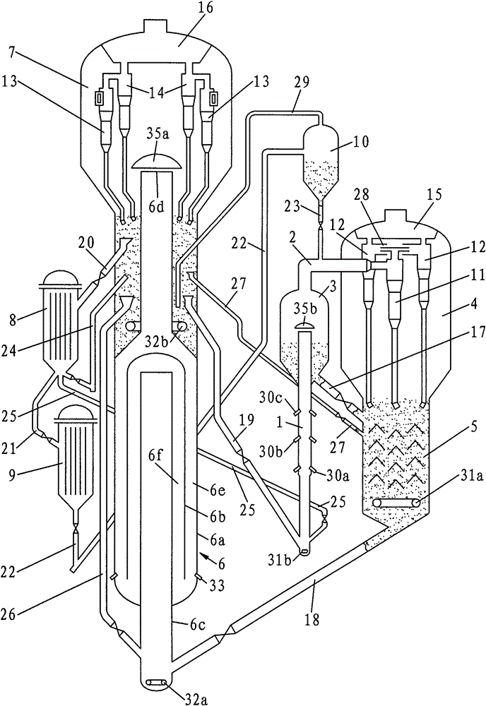
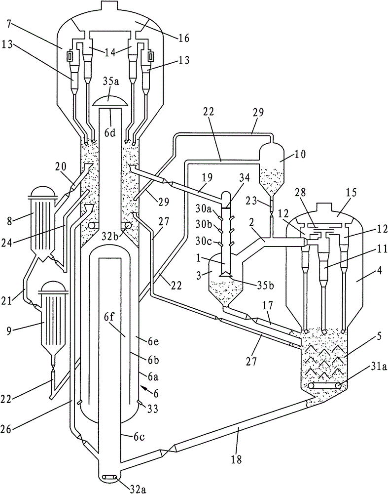
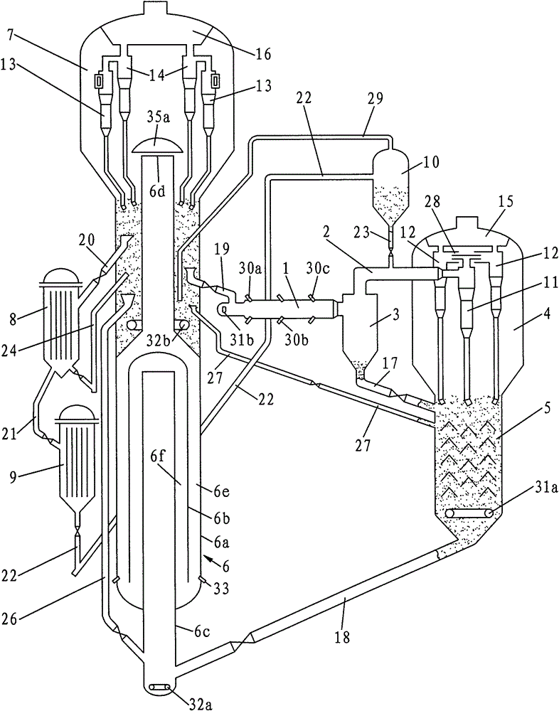
[0084] Embodiments similar to the present invention figure 1 The fluidized catalytic cracking pilot plant of the device shown is partly carried out according to the specific implementation method figure 1 The relevant description of the device shown is tested, the difference is that the first tubular reactor is equipped with two layers of heavy oil feed nozzles, and there is no regenerated catalyst delivery pipe between the dense phase section and the upper part of the stripping section of the turbulent bed regenerator. The design capacity of the first tubular reactor and the second tubular reactor is 60kg / d.

[0085] In the embodiment, the heavy oil raw material processed by the first tubular reactor is the same Daqing atmospheric residue as the comparative example, and the catalyst adopts the same CC-20D catalytic cracking industrial equilibrium catalyst as the comparative example. The feed refers to Daqing atmospheric residue and re-refined oil for the first tubular reacto...


PUM

PropertyMeasurementUnit
lengthaaaaaaaaaa
lengthaaaaaaaaaa
lengthaaaaaaaaaa

Abstract

The invention discloses a fluid catalytic cracking device in a petrochemical industry. The device mainly comprises a first tubular reactor with reaction section length of 5-15m, a second tubular reactor with reaction section length of 5-10m, a sedimentation device, a gas-solid separator, a regenerator composed of a baffle pipe-type separator and a turbulent bed separator, a first-grade regenerated catalyst cooler, a second-grade regenerated catalyst cooler, a low-temperature regenerated catalyst tank and pipes connected to corresponding devices. The baffle pipe-type separator mainly comprises a housing, an outer pipe and an inner pipe. The housing comprises a housing pipe, a transition section and an outlet pipe connected in series from top to bottom. Circular passages are formed between the housing pipe and the outer pipe and between the outer pipe and the inner pipe. The separator wall at the bottom of the inner pipe is provided with a regenerated catalyst inlet and an inlet of a catalyst to be regenerated. The separator wall at the bottom of the housing pipe is provided with a main air inlet pipe. The device can be used for heavy oil catalytic cracking and gasoline catalytic modification.

Description

technical field [0001] The invention relates to a fluid catalytic cracking device in the petrochemical industry. Background technique [0002] At present, the conventional fluidized catalytic cracking units used in the petrochemical industry generally have the following shortcomings: First, the use of a turbulent bed regenerator or a regenerator combined with a turbulent bed and a fast bed has relatively low coke intensity . Limited by the regeneration kinetics, the regeneration temperature is relatively high, resulting in a relatively high temperature of the regenerated catalyst participating in the reaction (generally around 700°C). Due to the limitation of the heat balance of the device, the ratio of agent to oil in the riser of heavy oil is relatively small, generally the total ratio of agent to oil is 5 to 8 (the total ratio of agent to oil in the riser is the weight circulation of the catalyst in the riser and the feed of each strand of the riser The ratio of the sum...

Claims


Application Information

Patent Timeline
Patent Type & Authority Applications(China)
IPC IPC(8): C10G55/06
Inventor 陈曼桥武立宪王文柯樊麦跃汤海涛
Owner LUOYANG PETROCHEMICAL ENG CORP SINOPEC
Why Eureka
Try Eureka