Suspension bridge superstructure demolition and replacement installation method

An installation method and suspension bridge technology, applied in suspension bridges, bridges, bridge maintenance, etc., can solve the problems of unstable, slow, and hidden safety hazards of catwalks, and achieve the effect of small damage to the main cable.

Active Publication Date: 2016-08-24
CCCC ROAD & BRIDGE SPECIAL ENG
View PDF10 Cites 6 Cited by
  • Summary
  • Abstract
  • Description
  • Claims
  • Application Information

AI Technical Summary

Problems solved by technology

At present, the new construction technology of suspension bridges is relatively mature, but when installing the upper structure, cable cranes are usually used as hoisting equipment, and catwalks need to be erected as construction platforms, and catwalks are very unstable in the air, posing a greater safety hazard. The cable crane is very heavy and moves slowly, resulting in a long period of superstructure installation
At present, the maintenance and reinforcement of suspension bridges are mainly focused on minor repairs. A small number of suspension bridges are reinforced by adding cable-stayed cables and other methods to change the structural stress system and have achieved good engineering results. There are few technical studies on superstructures such as suspenders and stiffened beams

Method used


Image

  • Suspension bridge superstructure demolition and replacement installation method
  • Suspension bridge superstructure demolition and replacement installation method
  • Suspension bridge superstructure demolition and replacement installation method

Examples


Embodiment Construction

[0026] The present invention will be further described in detail below in conjunction with the accompanying drawings and specific embodiments to facilitate a clear understanding of the present invention, but they do not limit the present invention.

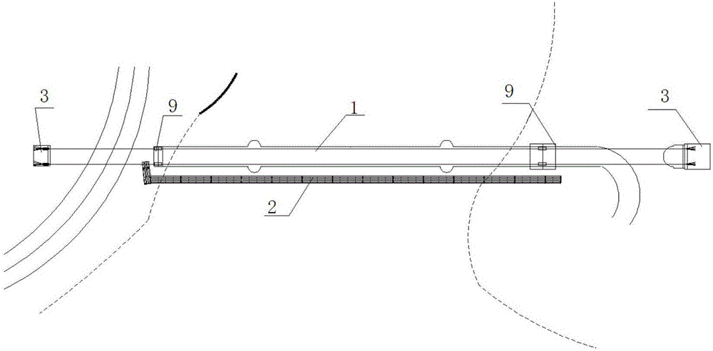
[0027] Such as figure 1 As shown, the present invention is a suspension bridge superstructure removal and replacement installation method,

[0028] The specific implementation steps are as follows:

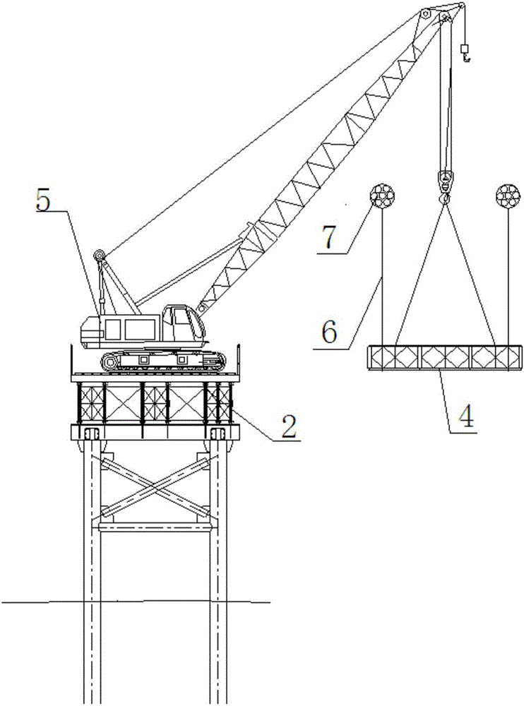
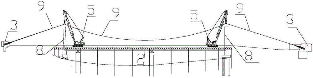
[0029] step one:. A trestle 2 is set up at a position 2m to 3m away from the outer side of the suspension bridge 1 . The trestle is parallel to the suspension bridge 1 and is used for the temporary passage of pedestrians and vehicles and the trestle 2 for hoisting and transporting platforms. The trestle 2 is connected to the roads (approach bridges) at both ends of the suspension bridge 1; the end of the trestle is bent toward the suspension bridge and fixed on one side of the cable tower of the suspension bridge to ensure the stab...


PUM


Abstract

The invention provides a suspension bridge superstructure demolition and replacement installation method. The suspension bridge superstructure demolition and replacement installation method comprises the following steps: a. erecting a trestle in parallel with a suspension bridge on the outer side of the suspension bridge, wherein the two ends of the trestle are connected with bridge approaches at the two ends of the corresponding suspension bridge; b. inspecting anchorages at the two ends of the suspension bridge and making sure that the anchorages are in a normal working state; c. demolishing original stiffening girders at an upper portion of the suspension bridge section by section; d. demolishing original suspenders and original cable clamps corresponding to the original stiffening girders; e. lifting a main cable through a crawler crane to realize the demolition of the original main cable at the upper portion of the suspension bridge; f. lifting a new main cable through the crawler crane to realize installation; g. installing new cable clamps and new suspenders at corresponding positions through surveying and setting-out; h. lifting each new stiffening girder section to a designated position by section through the crawler crane, and after all new stiffening girder sections are completely installed, connecting all sections to form an integral body. The suspension bridge superstructure demolition and replacement installation method shortens the demolition and replacement construction period of the suspension bridge superstructure to the utmost extent, and reduces the negative influence caused by the demolition and replacement of the suspension bridge superstructure.

Description

technical field [0001] The invention belongs to the field of bridge maintenance and construction, and in particular relates to a method for dismantling, replacing and installing the upper structure of a suspension bridge. Background technique [0002] Suspension bridges (plain areas) are widely used in bridges because of their good applicability and aesthetics. The peak period of its domestic development began in the 1990s. In recent years, a small number of suspension bridges have suffered from diseases, mainly due to the corrosion, corrosion and broken wires of the main cables and suspenders of the upper structure, and the damage of stiffening beams. It can be predicted that with the increase of the service life, the diseases of the suspension bridge will appear one after another, and the research on the maintenance and reinforcement of the upper structure of the suspension bridge, as well as the rapid dismantling and replacement technology will be of great practical signi...

Claims


Application Information

Patent Timeline
Patent Type & Authority Applications(China)
IPC IPC(8): E01D22/00E01D11/02
CPCE01D11/02E01D22/00
Inventor 李凡生盛海军侯德鹏高文波刘昂陈林
Owner CCCC ROAD & BRIDGE SPECIAL ENG
Why Eureka
Try Eureka