Arrow-shaped check valve

A check valve, arrow-shaped technology, applied in the direction of wellbore/well valve device, wellbore/well parts, sealing/packing, etc., can solve the problems of affecting spring life, short service life, waste of energy, etc., to achieve The effect of prolonging the service life, improving the service life and improving the sealing effect

Active Publication Date: 2016-08-24
MUDANJIANG XINBEIFANG PETROLEUM DRILLING TOOL +1
View PDF7 Cites 8 Cited by
  • Summary
  • Abstract
  • Description
  • Claims
  • Application Information

AI Technical Summary

Problems solved by technology

[0003] 1. Due to the existence of the pressure cap used to fix the valve seat, the passage of drilling fluid is limited, the flow area of ​​the arrow check valve is reduced, and a large resistance is generated, which causes a large pressure drop of the mud and wastes energy. Affect drilling efficiency
[0004] 2. The rubber ring used for sealing on the arrow-shaped spool is easy to wear, fail or fall off under the action of high-pressure and high-speed fluid, which affects the sealing effect of the arrow-shaped spool
[0005] 3. As the pressure value of the drilling fluid fluctuates up and down, the spring of the arrow-shaped spool keeps beating during normal operation, which affects the life of the spring and is not good for well control operations
[0006] Chinese patent document CN 203362113 U discloses an arrow-shaped check valve, which improves the problem of short service life by arranging hard alloy sealing sleeves on the arrow-shaped valve core and valve seat, but the structure is relatively complicated and has not yet been solved Problems with small flow area and jumping arrow-shaped spool
Due to the structural defect of the set safety snap ring, when a well kick or blowout occurs, the safety snap ring is easy to lock the arrow-shaped valve core, and it is difficult to disengage

Method used


Image

  • Arrow-shaped check valve
  • Arrow-shaped check valve
  • Arrow-shaped check valve

Examples


Embodiment Construction

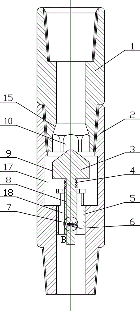
[0030] like Figure 1~6 Among them, an arrow-shaped check valve, including an upper valve body 1 and a lower valve body 2 connected to each other, the upper valve body 1 is provided with a through hole, and the bottom of the through hole is sequentially provided with a cone that expands in diameter relative to the through hole. Shaped surface 15 and first splined surface 10;

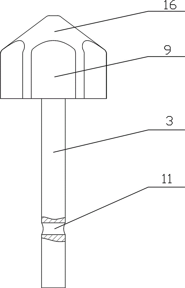
[0031] In the lower valve body 2, there is an arrow-shaped spool 3 that slides axially along the lower valve body 2, and the top of the arrow-shaped spool 3 is provided with a conical frustum 16 that is sealingly matched with the conical surface 15, and is connected with the first spline surface 10. The second splined face 9 for a sealing fit.

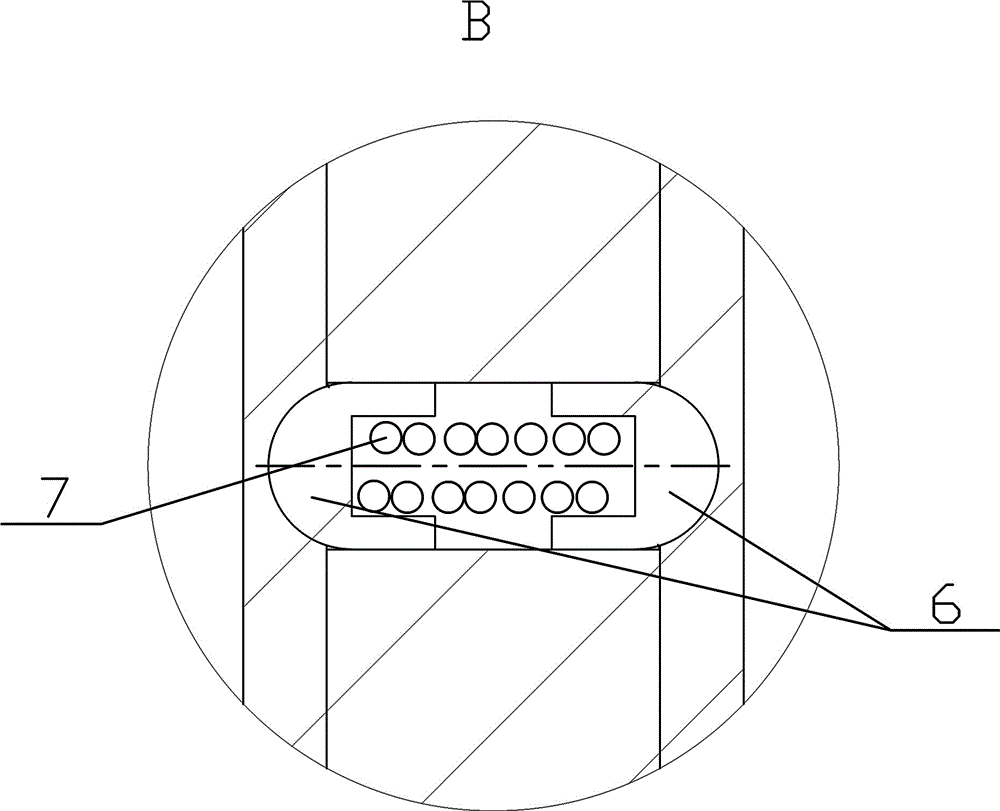
[0032] In a preferred solution, the first splined surface 10 is a cylindrical through-hole with a plurality of arc-shaped protrusions or depressions on the inner wall. In this example, a structure in which the inner wall of the through hole is provided with a p...


PUM


Abstract

The invention provides an arrow-shaped check valve. The arrow-shaped check valve comprises an upper valve body and a lower valve body which are connected with each other. A through hole is formed in the upper valve body, and a conical surface and a first spline surface are arranged at the bottom of the through hole in sequence. An arrow-shaped valve element sliding in the axial direction of the lower valve body is arranged in the lower valve body, and a frustum in sealing fit with the conical surface and a second spline surface in sealing fit with the first spline surface are correspondingly arranged at the top of the arrow-shaped valve element. According to the arrow-shaped check valve, by the adoption of the spline surface structure, the open area is increased and exceeds the original open area by 1.5-2 times on the premise of not increasing the stroke or the outer diameter; by the adoption of the combination scheme of conical surface and spline surface fit, the sealing effect is improved; especially, by the adoption of the scheme, it is unnecessary to arrange additional sealing elements such as sealing rings, sealing cylinders and other structures made of rubber, so that it is avoided that sealing elements are rapidly abraded by high-pressure mud, and the service life of the arrow-shaped check valve is prolonged.

Description

technical field [0001] The invention relates to the field of tools for oil and gas exploitation and drilling, in particular to an arrow-shaped check valve for drilling tools. Background technique [0002] When drilling on the drilling platform, due to the complex and changeable formation, high-pressure fluid in the formation is often encountered during the drilling process. If there is no reliable blowout prevention system, kick or blowout may occur, which will affect the safety of drilling operations and drilling efficiency. The arrow-shaped check valve is a blowout prevention tool in the drill string. It is connected to the drill string. When encountering high-pressure oil and gas layers, it can drive the arrow-shaped valve core to move upwards and seal with the valve seat, closing the drill string. Inner channel to prevent blowout and well kick. The disadvantages of arrow check valves in the prior art are: [0003] 1. Due to the existence of the pressure cap used to fix...

Claims


Application Information

Patent Timeline
Patent Type & Authority Applications(China)
IPC IPC(8): E21B34/06E21B33/10
CPCE21B33/10E21B34/06
Inventor 邓福成江友亮
Owner MUDANJIANG XINBEIFANG PETROLEUM DRILLING TOOL
Why Eureka
Try Eureka