Telescopic steel frame joint suitable for large tunnel deformation

A large deformation, steel frame technology, applied in tunnels, tunnel linings, shaft linings, etc., can solve problems such as reducing the initial support bearing capacity, large safety risks, and inability to effectively control the range of expansion and contraction.

Active Publication Date: 2016-08-24
CCCC FOURTH HARBOR ENG CO LTD +2
View PDF10 Cites 1 Cited by
  • Summary
  • Abstract
  • Description
  • Claims
  • Application Information

AI Technical Summary

Problems solved by technology

[0004] The steel frame is the most effective means to support the surrounding rock, and is widely used in tunnels with large deformations. However, the steel frames currently used are mainly rigidly connected, and will twist or even shear as the deformation continues to increase after the large deformation occurs. The shear failure greatly reduces the bearing capacity of the primary support, the deformation of the surrounding rock cannot be effectively suppressed, and the surrounding rock often deteriorates further. In order to ensure the safety of the tunnel structure and meet the building limits, the primary support can only be removed Reconstruction, resulting in great safety risks and high construction costs
[0005] Aiming at this problem of the steel frame, telescopic steel frames have been developed at home and abroad. There is a certain amount of scalability, but the range of expansion and contraction cannot be effectively controlled, and the ultimate bearing capacity of the steel frame cannot be controlled. effective protection

Method used


Image

  • Telescopic steel frame joint suitable for large tunnel deformation
  • Telescopic steel frame joint suitable for large tunnel deformation
  • Telescopic steel frame joint suitable for large tunnel deformation

Examples


Embodiment Construction

[0014] Below, the structure of the present invention will be further described in detail in conjunction with the drawings and embodiments.

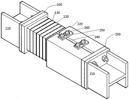
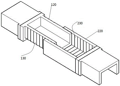
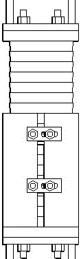
[0015] Depend on Figure 1 ~ Figure 3 It can be seen that the telescopic steel frame joint suitable for the large deformation of the tunnel in the present invention is composed of two coupled parts, the upper part 100 and the lower part 200. Both the upper part 100 and the lower part 200 have a joint for connecting with the steel frame, that is, the upper joint 110 and the lower coupling head 210; the upper part 100 has a convex body end 120, and the outer surface of the convex body end has a barb-shaped barb 130; the lower part 200 has a fitting cavity 220 that can fit with the upper convex body end 120, and the fitting cavity The inner surface also has barb-shaped reverse barbed teeth 230; the fitting cavity 220 is provided with a slit 240; the connecting steel plate 250 spans both sides of the slit and is connected with the fitting cav...


PUM


Abstract

The invention discloses a telescopic steel frame joint suitable for large tunnel deformation. The joint consists of two parts, namely an upper part (100) and a lower part (200) which are coupled with each other; both the upper part (100) and the lower part (200) are provided with coupling heads connected with a steel frame, namely an upper coupling head (110) and a lower coupling head (210); the upper part (100) is provided with a convex body end (120), and barbed inverted teeth (130) are arranged on the outer surface of the convex body end; the lower part (200) is provided with a sheathing cavity (220) capable of being sheathed with the convex body end (120) of the upper part, and barbed reverse inverted teeth (230) are arranged on the inner surface of the sheathing cavity; a gap (240) is formed in the sheathing cavity (220); each of connecting steel plates (250) transversely spans the two sides of the gap and is connected with the sheathing cavity through a bolt. The telescopic steel frame joint disclosed by the invention is suitable for various forms of excavation methods and can be processed and mounted with the finished steel frame on site, the length of the steel frame is automatically adjusted according to the stress situations, the telescopic amount and the ultimate bearing capacity of the steel frame can also be manually set at the beginning, the telescopic amount can be locked during construction, and the stress of the steel frame and the deformation of surrounding rocks can be effectively controlled to ensure the safety and the stability of a tunnel structure.

Description

technical field [0001] The invention relates to the field of steel frame reinforcement equipment for tunnels and underground structures, in particular for connecting joints with finished steel frames in the initial support of large deformation of tunnel structures. Background technique [0002] According to relevant data, with the continuous and rapid development of my country's railway and highway construction, weak and large deformation tunnel projects continue to emerge. The large deformation of the tunnel is an extremely difficult technical problem encountered in the tunnel construction process. The consequence of the large deformation is not only a safety problem during the tunnel construction process, but also a huge safety hazard in the later operation. [0003] At present, the main technical measures for large deformation of tunnels include reservation of deformation, strengthening of primary support or temporary support, and early application of secondary lining to ...

Claims


Application Information

Patent Timeline
Patent Type & Authority Applications(China)
IPC IPC(8): E21D11/22
CPCE21D11/22
Inventor 张俊儒冯冀蒙许伦锋张伟张梅崔耀李洪涛
Owner CCCC FOURTH HARBOR ENG CO LTD
Why Eureka
Try Eureka