Launch canister based on carbon fiber composite base material and manufacturing method

A launch tube, carbon fiber technology, applied in the direction of launch devices, etc., can solve the problems of discontinuous manufacturing and material properties, cumbersome process implementation, low production efficiency, etc., to achieve good interface continuity, strong process operability, and high production efficiency. Effect

Pending Publication Date: 2020-07-24
HENGSHEN
View PDF0 Cites 3 Cited by
  • Summary
  • Abstract
  • Description
  • Claims
  • Application Information

AI Technical Summary

Problems solved by technology

[0003] At the present stage, the composite launch tube structure often adopts a multi-layer structure mixed with various materials such as carbon fiber, glass fiber, and erosion-resistant rubber. delamination

Method used


Image

  • Launch canister based on carbon fiber composite base material and manufacturing method
  • Launch canister based on carbon fiber composite base material and manufacturing method
  • Launch canister based on carbon fiber composite base material and manufacturing method

Examples


Embodiment 1

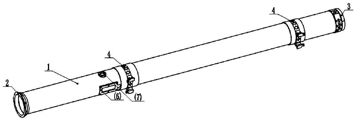
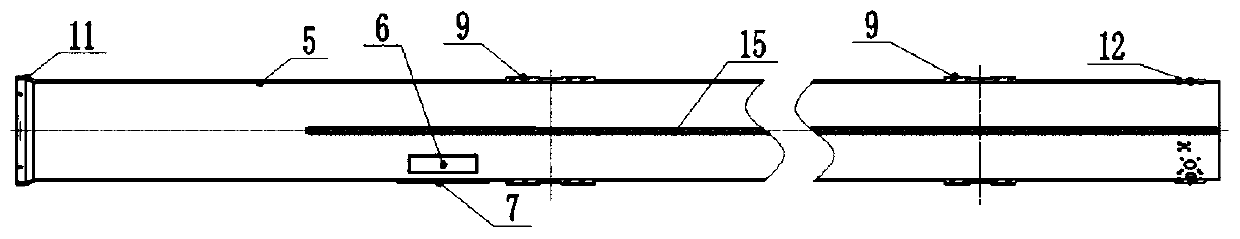
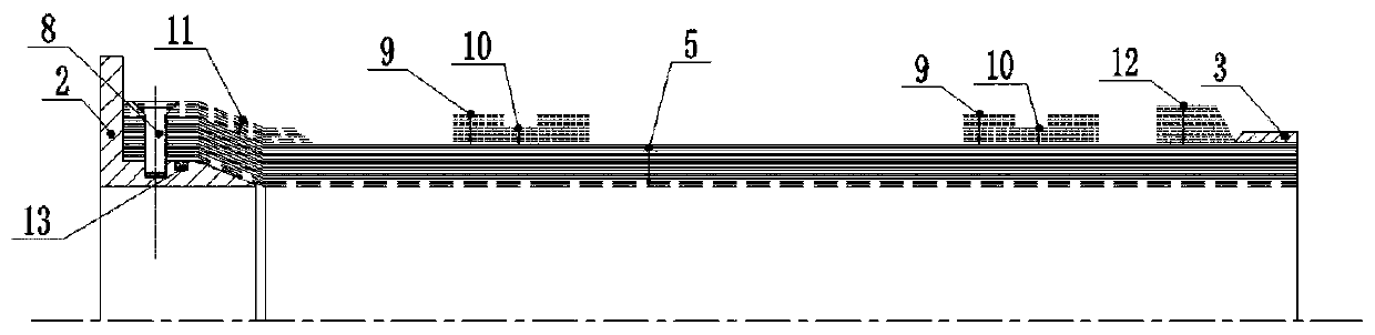
[0033] Example 1, such as Figure 1-6 The launch tube designed and manufactured by the present invention shown has a main structure launch tube 1 comprising an ablation-resistant prepreg layer 14, an ablation-resistant layer 16, a first flame-retardant and toughened layer 17, and a second Two flame retardant and toughening layers 18 , between the ablation-resistant prepreg layer 14 and the ablation-resistant layer 16 , there is also a guide plate 15 laid along the length direction of the emitting cylinder 1 .

[0034] The ablation-resistant prepreg layer 14 is a phenolic resin prepreg layer, and the ablation-resistant layer 16, the first flame-retardant and toughened layer 17 and the second flame-retardant and toughened layer 18 are made by adopting carbon fiber wet winding method Manufactured, the ablation-resistant layer 16 and the first flame-retardant and toughened layer 17 are spirally wound at an angle of ±23°, and the inside of the second flame-resistant and toughened l...

Embodiment 2

[0060] The difference between this embodiment and Embodiment 1 is that the helical winding angle of the cylinder is increased, thereby reducing the thickness ratio of the helical winding, the weight remains unchanged, the strength of the cylinder is enhanced, and the ability to resist internal pressure is increased.

[0061] A method for making a launch tube, comprising the steps of:

[0062] Step 1: Use the TF1726 / HFW196PA-D6 / 50 phenolic prepreg of Jiangsu Hengshen Co., Ltd. as the ablation-resistant prepreg layer 14 located in the innermost layer of the cylinder. After pre-compaction, use phenolic prepreg TF1726 / HFW196PA-D6 / 50 to lay out the guide plate 15 along the length direction of the barrel. After that, the ablation-resistant layer 16 of the cylinder is formed by carbon fiber wet winding technology. The resin is selected from the TF1726 phenolic resin of Jiangsu Hengshen Co., Ltd., and the carbon fiber is selected from the HF30S type (equivalent to Toray T700S) fiber o...


PUM

PropertyMeasurementUnit
thicknessaaaaaaaaaa
thicknessaaaaaaaaaa
thicknessaaaaaaaaaa

Abstract

The invention discloses a launch canister based on a carbon fiber composite base material and a manufacturing method. The launch canister comprises a launch canister body, wherein the launch canisterbody comprises an ablation resistance preimpregnated layer, an ablation resistance layer, a first flame-retardant toughening layer and a second flame-retardant toughening layer which are arranged in sequence from inside to outside; and a guide plate is paved between the ablation resistance preimpregnated layer and the ablation resistance layer in the length direction of the launch canister body. The manufacturing method of the launch canister is simple, is easy to implement, has strong process operability, and fully utilizes different types of carbon fibers. By adopting the manufacturing method, even if the body of the launch canister is made of carbon fibers having the common strength, the body of the launch canister still has excellent mechanical properties, and the cost can be reduced.Compared with an existing metal multi-layer structure and other multi-layer structures made of mixed carbon fibers, glass fibers and the like, the launch canister based on the carbon fiber composite base material has the advantages that the weight of the launch canister based on the carbon fiber composite base material is reduced, and the launch canister based on the carbon fiber composite base material has good interface continuity and excellent mechanical properties, and meets the requirements for axial stiffness and stability.

Description

technical field [0001] The invention belongs to the field of launching tube manufacture, and in particular relates to a launching tube based on carbon fiber composite base material and a manufacturing method thereof. Background technique [0002] The lightweight of airborne equipment is of great value in terms of energy saving. At present, airborne equipment is mostly made of aluminum alloy, which has a large weight, high manufacturing cost, and low storage life. Compared with other materials, carbon fiber composite materials have the characteristics of light weight, high specific strength and specific modulus, corrosion resistance, fatigue resistance, and environmental resistance, and are widely used in various fields. Therefore, the composite material launcher emerges at the historic moment. [0003] At the present stage, the composite launch tube structure often adopts a multi-layer structure mixed with various materials such as carbon fiber, glass fiber, and erosion-res...

Claims


Application Information

Patent Timeline
Patent Type & Authority Applications(China)
IPC IPC(8): F41F1/00
CPCF41F1/00
Inventor 高露露仇亚萍孟梦陈明新刘伟
Owner HENGSHEN
Why Eureka
Try Eureka